If a FIXED output like tape 1 or tape 2 is used, it is independent of the volume setting of the
receiver/pre-amplifier thus allowing the OnQ A-BUS
Volume Controls to have full control over the sound
level. See Figure 1.
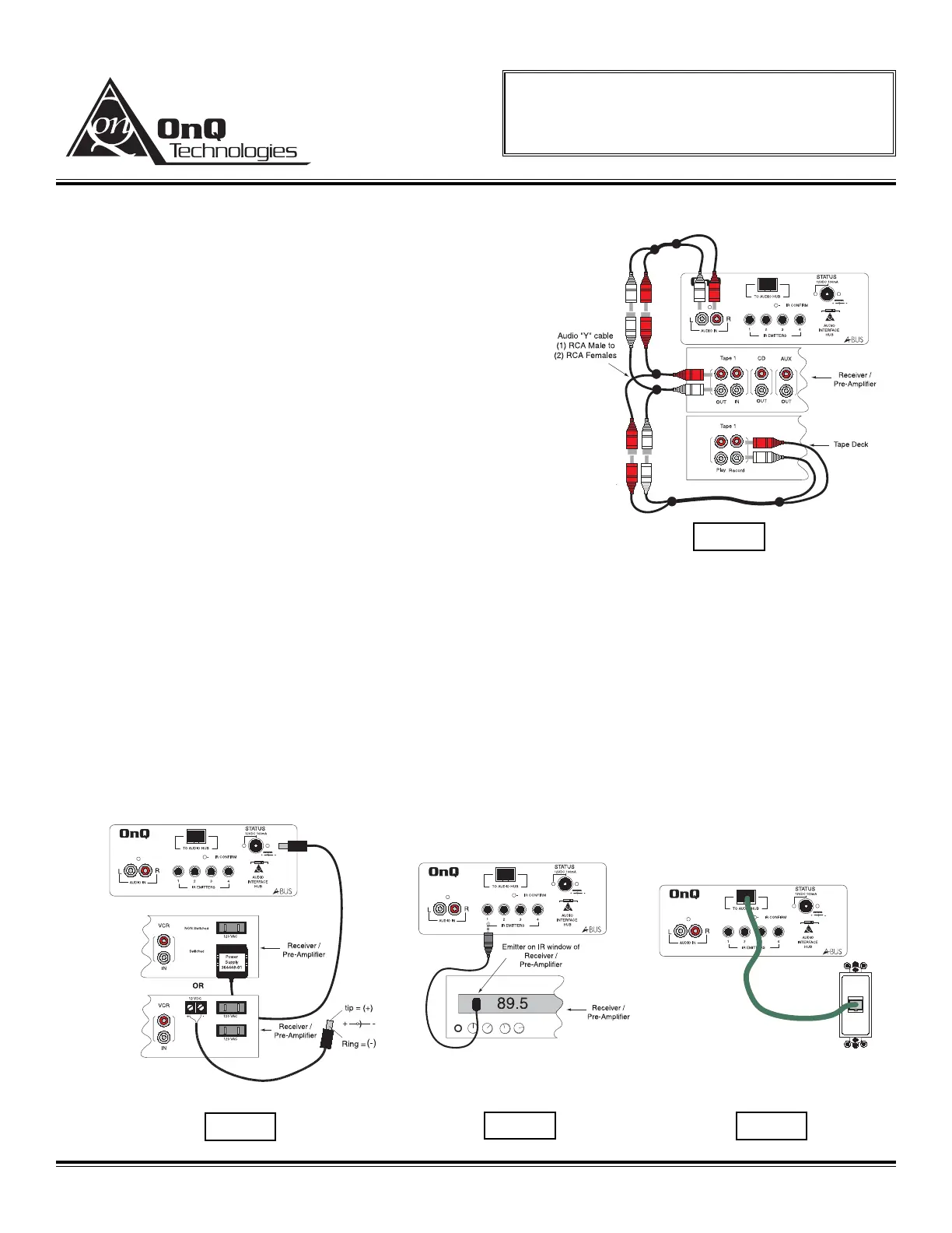
NOTE: If the TAPE OUTPUT jack is used and must be
shared with a Tape Deck, then audio Y cables can be
used. See figure 2.
C. To monitor “true” power status of the source
equipment connect a 12 VDC power supply (P/N
364488-01) from a switched output jack of the
receiver/pre-amplifier to the Status input jack. Place
the Bypass/Status Switch in “Status” position. If the
receiver/pre-amplifier has a switched 12 VDC output it
can be used in place of the OnQ A-BUS Status Power
Supply. A 3.5mm phone plug will be needed and
configured with the “tip” positive and “ring” negative.
See figure 3.
NOTE: If “true” status monitoring is to be used, see the OnQ A-Bus Volume Control Instruction Sheet to set the
status jumper to the ENABLE position.
D. If IR control is being used plug the emitters into the IR EMITTER outputs and place them onto the IR
receiver windows of the source equipment via the peel away adhesive strip. See figure 4.
E. Connect the Source input unit via a CAT5 jumper such as the OnQ 36” (P/N 363201-30) to a wall jack
with an RJ-45 insert. This jack in turn should be wired to the input of the OnQ A-BUS 4 Zone
Distribution Hub. See figure 5.
F. Check all other system components and then power the OnQ A-BUS 4 Zone Distribution Hub.
OnQ Technologies, Inc.
P.O. Box 60907
Harrisburg, PA 17106-0907
800-321-2343
www.onqtech.com
Installation/Instruction Sheet
A-Bus Source Input Unit
IS-0148 Rev. B
IS-0148 Rev. B Page 2 of 2
Ref. P/N 100225-48
 Loading...