11 OPAL-RT Technologies OP5600/OP5650 User Manual
OP5600 Series/OP5650 Simulator
Hardware Configuration
HARDWARE CONFIGURATION
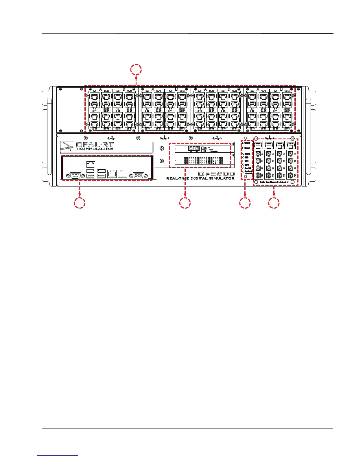
The interfaces on the front of the OP5650 Artix 7 (OP5143) include 4 RJ45 monitoring panels.
A
E D C B
Figure 3: OP5650 front connector panels
A. 4 panels of RJ45 connectors provide connections to monitor output from mezzanine I/O
boards. Each connector is linked to front and b0ack mezzanines on the carrier board. Analog
mezzanines (channels 0-16) will use only the first column of connectors. Digital mezzanines will
use both columns (channels 0-15 in the first column and channels 16-31 on the second column
of connectors). See the mezzanines connector image and the RJ45 pinouts for more detailed
information.
B. Monitoring RJ45 connectors with mini-BNC terminals: RJ45 cables connect from a channel on an
RJ45 panel (B) to one of four RJ45 monitoring connectors (C). Mini-BNC connectors allow for quick
cable connections to monitoring devices (such as an oscilloscope). See “connecting monitoring
devices” for details.
 Loading...