FRONT END ALIGNMENT
3C-23
ing geometry, the following checks and inspections
must be made to insure correctness of alignment
equipment readings and alignment adjustments.
1. The front tires should have approximately the
same wear and all tires must be inflated to specified
pressures (see Wheel and Tire Specifications
-
Sec-
tion 3G).
2. Check front wheel bearings for looseness and ad-
just if necessary (see Front Suspension Adjustments
-
Section 3A).
3. Check for run-out of wheels and tires, (see Section
3G).
4. Check wheels and tires for balance and correct if
out-of-balance (See Section 3G).
5. Check for looseness at ball joints and tie
rdd ends;
if found excessive, it must be corxcted before align-
ment readings will have any value.
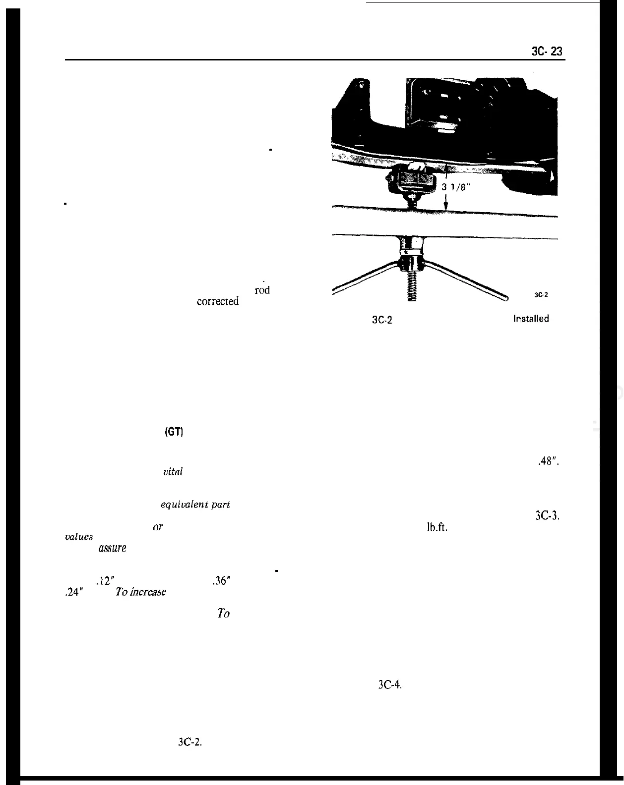
Figure
SC-Z
Spring Compressor J-2 1689 Installed
6. Check shock absorber action and correct if neces-
sary. Consideration must be given the optional
equipment on the car, undercoating, dirt, etc.
7. It is advisable to check the condition and accuracy
of any equipment being used to check front end
alignment and to make certain that instructions of
the manufacturer are thoroughly understood.
ADJUSTING CASTER
(GT)
4. Remove upper control arm shaft,
5. Remove upper control arm from shock absorber
support, being careful not to lose toothed washers.
6. Adjust caster by installing selective toothed wash-
ers on both sides of control arm shaft, between con-
trol arm and shock absorber support. Never use
CAUTION: Front suspension fasteners are impor-
more than one washer at any one location. The total
tant attaching parts in that they could
affect thickness, front and rear washer, must equal
.48”.
the performance of
uital
components and sys-
tems, and/or could result in major repair expense.
There are only two possible caster changes that can
be made.
They must be replaced with one of the same
part
number or with an
equiualentpart
ifreplacement
becomes necessary. Do not use a replacement part
Of lesser quality
or
substitute design. Torque
values
must be used as specified during reassem-
bly to
mure
proper retention of these parts.
7. Using a drift to align holes, replace control arm
shaft in the direction as shown in Figure
3C-3.
Torque hex nut to 33
lb.ft.
Make certain that crown
of both plate washers shows outward.
To change caster, three washers are available
-
one
with a
.12”
thickness, one that is
.36”
thick, and one
.24”
thick. Toincrease caster place one of the thin
washers at the front of the control arm shaft and one
of the thick washers at the rear.
To decrease caster
place one thick washer at the front of the control
arm shaft and one thin washer at the rear.
1. Position jack below front suspension cross mem-
ber and raise front end of car.
8. Remove spring compressor, and install front
wheel and torque wheel nuts to 72 ft. Ibs.
9. Recheck caster.
ADJUSTING CASTER (OPEL 1900. MANTA)
2. Place jack stands below front frame side members
and remove front wheel on side which caster is to be
adjusted.
1. Jack up vehicle and remove front wheel on the side
on which caster is to be adjusted.
3. Install front spring compressor J-21689 and com-
press spring. See Figure
3C-2.
2. Support vehicle below both lower control arms.
See Figure
3C-4.
3. Unscrew hex nut from upper control arm shaft
and pull out shaft.
4. Adjust caster by replacing washers (A) (front) and
 Loading...