GT STEERING COLUMN ASSEMBLY
3E- 45
loose must never be done. The only recommendation
for freeing frozen steering wheels is to use a penetrat-
ing lubricant.
Installation
1. Before installing steering wheel, lubricate return
pin and slide area on direction signal switch return
cams and horn ring contact.
2. With steering wheel properly aligned to shaft, in-
stall lockplate and nut. Torque nut to 15
Ib.ft.
CAUTION:
This steering wheel to steering shafi fas-
tener is an important attac&ng part in that it could
affect the performance of vital components and sys-
tems, and/or could result in major repair expense. It
must be rep/aced with one of the same part number
or with an equivalent part, if replacement becomes
necessary. Do not use a replacement part of lesser
quality or substitute design. Torque values must be
used as specified during reassembly to assure proper
retention of this part.
3. Bend up lockplate tab and install horn cap.
4. Reconnect battery.
REMOVAL AND INSTALLATION OF IGNITION
LOCK CYLINDER
Removal
This procedure may be performed with the steering
column assembly either removed or installed in the
car.
1. Remove steering wheel, as outlined previously in
this Group.
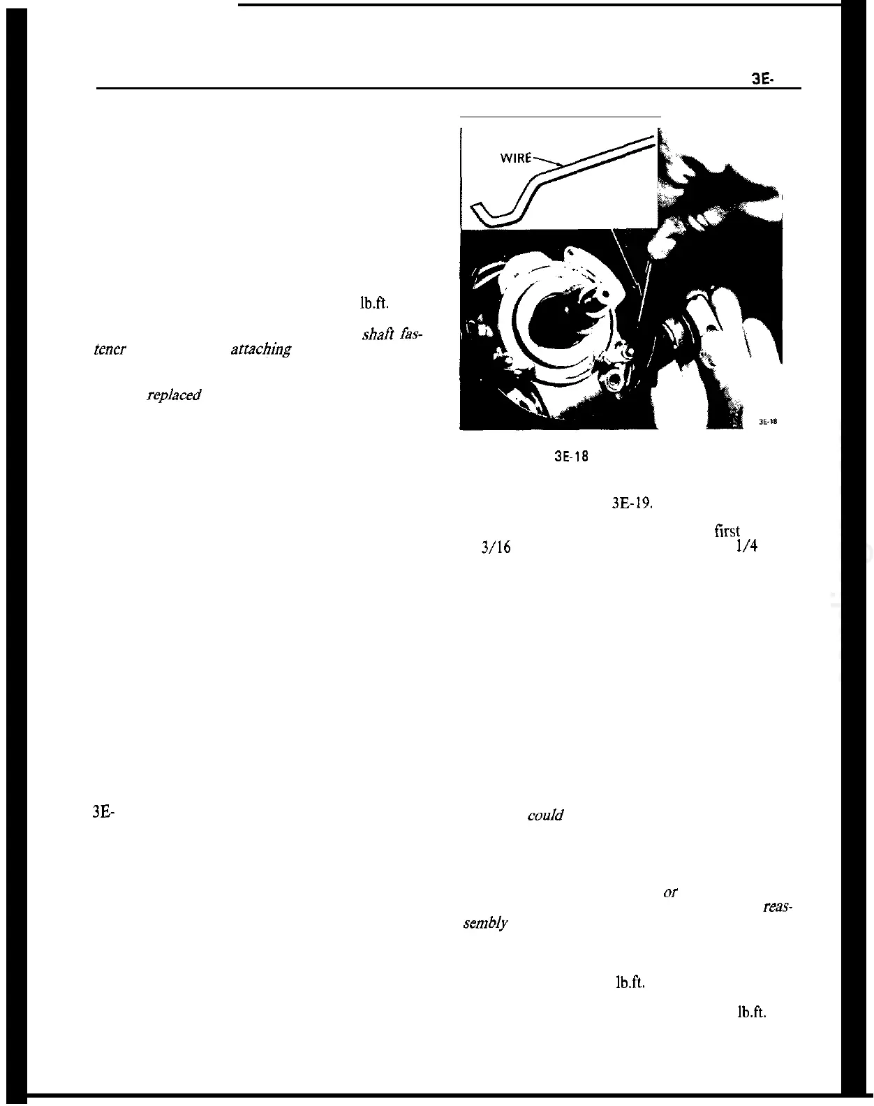
2. Position lock cylinder to run position.
3. Using suitable piece of wire, push in lock cylinder
retaining pin and remove lock cylinder. See Figure
3E- 18.
Installation
1. Insert lock cylinder into lock cylinder housing.
2. Install steering wheel, as outlined previously in
this section.
REMOVAL AND INSTALLATION OF STEERING
COLUMN ASSEMBLY
Removal
1. Position steering so that front wheels are straight
ahead.
Figure
3E-18
Removing Lock Cylinder
2. Loosen steering shaft upper universal joint lower
clamp bolt. See Figure
3E-19.
3. Drill off heads of both tear bolts by first drilling
an 3/16 inch pilot hole and then inserting a
l/4
inch
bolt extractor to remove lockbolt.
4. Disconnect ignition (white) and direction signal
(black) wire set plugs.
5. Support steering column assembly and remove
both hex. head bolts.
6. Pull steering column assembly off center steering
shaft. Do not apply any force as plastic injections in
center steering shaft may be loosened and shaft
would then require replacement.
Installation
CAUTION:
Fasteners are important attachingparts in
that they cooId affect the performance of vital com-
ponents and systems, and/or could result in major
repair expense. They must be replaced with one of
the same part number or with an equivalent part if
replacement becomes necessary. Do not use a re-
placement part of lesser quality
or
substitute design.
Torque values must be used as specified during
reas-
sembIy to assure proper retention of these parts.
1. Install steering column assembly onto steering
shaft and torque steering shaft upper universal joint
lower clamp bolt to 14
lb.ft.
2. Install hex head bolts and torque to 14
lb.ft.
NOTE:
Be sure to install ground wire.