3A. 8 1973 OPEL SERVICE MANUAL
HOUSING
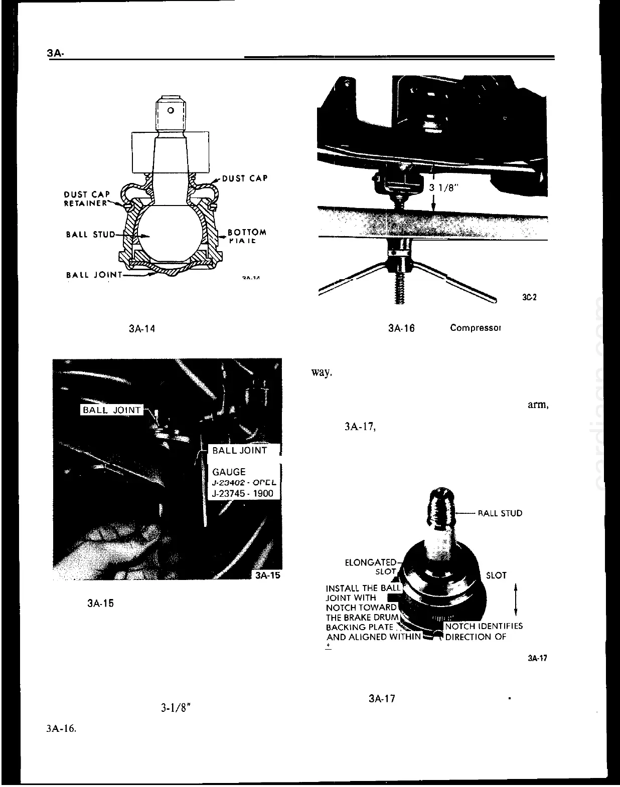
Figure
3A-14 Lower Ball Joint
1 CHECKING
I
Figure 3A-15 Ball Joint Checking Gauge Installed
3. Remove cotter pin from castle nut on ball joint
stud and back off castle nut two (2) turns. Hit ball
stud a sharp blow to break it loose. DO NOT
REMOVE NUT.
4. Install spring compressor (J-21689) and compress
spring until a distance of
3-l/8” is achieved between
spring compressor and lower spring leaf. See Figure
3A-16.
5. Disconnect shock absorber to lower control arm
\
3cz
Figure 3A-16 Spring Compressa
attachment bolt and swing shock absorber out of the
Way.
6. Remove castle nut from ball joint stud. Prior to the
removal of the lower ball joint from the control
arm,
note the position of the locating notch, shown in
Figure
3A-17, in the rim of the ball joint housing.
Scribe or mark the control arm to facilitate align-
ment of the replacement ball joint during installa-
tion.
DIRECTION OF
ELONGATED
-
2” OF THE LOWER
‘ELONGATED SLOT
CONTROL ARM CENTER LINE.
w-17
Figure 3A-17 Lower Ball Joint Notch
-
GT
7. Pry off dust cap retainer and remove dust cap
being careful not to damage it.