EasyManua.ls Logo

Opitec 107.388 - User Manual

Opitec 107.388
13 pages
Print Icon
To Next Page IconTo Next Page
Loading...
1
D107388#1
Premium-Line
Electro motor
107.388
Warning!
This product contains small parts that can be swallowed.
There is a danger of choking!
This product contains a magnet.
Swallowed magnets can block the intestines and cause
severe internal injury.
If a magnet is swallowed by accident contact a doctor as
soon as possible.
Please Note
The OPITEC range of projects is not intended as play
toys for young children.They are teaching aids for
young people learning the skills of Craft, Design and
Technolo- gy.These projects should only be undertak-
en and tested with the guidance of a fully qualified
adult. The finished projects are not suitable to give to
children under 3 years old. Some parts can be swal-
lowed. Dan- ger of suffocation!
Question and Answer IconNeed help?

Do you have a question about the Opitec 107.388 and is the answer not in the manual?

Overview

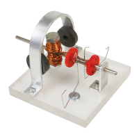
This document describes the OPITEC Premium-Line Electro motor, model number 107.388, a functioning model designed for educational purposes in Craft, Design, and Technology at Key Stage 4.

Function Description

The OPITEC Electro motor is a hands-on project designed to teach the principles of an electric motor. It allows users to construct a working model using various materials, primarily metal and plastic. The motor operates based on the interaction between permanent magnets and an electromagnet (coil) that becomes magnetic when current flows through it. As the coil rotates, a commutator mechanism reverses the current direction, causing the magnetic poles of the coil to change, which in turn creates continuous repulsion and attraction with the permanent magnets, resulting in rotation.

Important Technical Specifications

Materials:

  • Base: Acrylic, 8 x 70 x 70 mm.
  • Holder: Aluminium strip (2 x 10 x 250 mm) or holed strip metal (0.5 or 0.8 x 10 x 150 mm).
  • Shaft: Metal axle, Ø 3 x 95 mm.
  • Iron Core: Machine screw & nut, M6 x 25.
  • Winding: Varnished copper wire, Ø 0.6 x 2400 mm.
  • Commutator: Double gears, 30/10 Zähne (teeth).
  • Contacts: Spring steel, Ø 0.5 x 500 mm.
  • Permanent Magnets: Ring, Ø 18/5 x 5 mm (2 pieces).
  • Sundries: Machine screws (M3 x 16, M3 x 6), Nuts (M3), Washers (M4).
  • Jig: Beech wheel, Ø 40 x 10 mm.
  • Adhesive: Turbo glue (not included), available in 4g or 10g bottles.

Tools Required:

  • Cutting: Metal shears or side cutters (for holed metal, spring, copper wire), junior hacksaw (for bearings and U-shape holder).
  • Filing: Files (correct grade, needle files for small notches).
  • Sawing: Hacksaw.
  • Drilling: Pillar drill, 2.5 mm diameter drill bit (for plastic or metal), 3 mm diameter drill bit (for holder and bearings), 1 mm diameter drill bit (for commutator gears).
  • Tapping: 3-part drill and tap wrench or single cut tap (for M3 threads).
  • Other: Vice with soft jaws, pencil, centre punch, pliers, emery cloth, sellotape or insulating tape.

Usage Features

The construction process involves several stages:

  1. Making the Base: Marking and drilling 2.5 mm holes in the acrylic base, then tapping M3 threads.
  2. Making the Holder and Bearings: Users can choose between two versions:
    • Version 1 (Easier): Using pre-holed metal strip, which only requires bending.
    • Version 2 (More Challenging): Making the U-shaped holder from an aluminium strip, requiring marking, drilling, and bending. The manual details the aluminum strip version, including cutting, filing, drilling 3mm holes, and bending the holder using a wooden wheel as a former.
  3. Making the Core, Coil, and Commutator:
    • Drilling two 1 mm holes in one of the double gears for the commutator contacts.
    • Assembling the iron core by marking and drilling the bolt, inserting the shaft, and securing with a nut and glue.
    • Gluing the drilled double gear and a second gear onto the shaft, ensuring correct spacing and alignment (90 degrees to the bolt).
    • Winding the varnished copper wire around the bolt (iron core) in a doubled fashion, ensuring no kinks and even winding. The ends of the wire are then threaded through the holes in the gears to form the commutator contacts, with varnish removed from the ends.
    • Bending the spring steel contacts.
  4. Final Assembly and Testing:
    • Attaching the permanent magnets to the U-shaped holder, either by screwing or gluing, ensuring correct polarity.
    • Screwing the bearing strips to the base, ensuring the shaft rotates freely.
    • Mounting the U-shaped holder and contact springs, ensuring light contact with the copper wire.
    • Connecting the motor to a 4.5-volt battery and giving the rotor a light twist to initiate operation.

Maintenance Features

  • Lubrication: Apply a few drops of oil to the bearings and contacts to ensure smooth operation and reduce friction.
  • Cleaning: Keep the working area free from magnetic pieces during assembly.
  • Handling: Handle magnets carefully to avoid crushing or pinching injuries. Wear safety glasses when working with strong magnets, as they can splinter.
  • Storage: Keep magnets away from computers, electronic data, and heart pacemakers. Avoid storing magnets in atmospheres where there is a danger of explosion or in contact with hydrogen, which can cause deterioration.
  • Safety: The product contains small parts and magnets. There is a danger of choking and severe internal injury if magnets are swallowed. In case of accidental swallowing, contact a doctor immediately. Some magnets may have a nickel coating that can cause skin allergies; avoid contact if this occurs.
  • Transport: Special regulations apply for transporting magnets by air or post; consult the airline or Post Office.

This project is intended as a teaching aid for young people and should be undertaken with the guidance of a fully qualified adult. It is not suitable for children under 3 years old.

Opitec 107.388 Specifications

General IconGeneral
BrandOpitec
Model107.388
CategoryEngine
LanguageEnglish