Measuring up front wheels (‘Rider’ only)
The front wheels should have been properly
aligned on the factory oor, but will need periodic
adjustment. To adjust the rider’s wheels, begin
by making sure that neither of the front wheels
has any buckling in it. Buckling will bring error
into the necessary measurements and will result
in a relatively large error in the setup. Also
ensure all steering plates are securely fastened.
Once the rims have been made true, point
them straight ahead and measure the distance
between the leading edge of the inner side of the
brake rim on both wheels (L.E., gure 10.1), and
the distance between the trailing edge (T.E.) of
each inner side of both rims across the bicycle.
Take the average of these measurements,
subtract 2 mm, and this will be your guideline
2
.
Once you have taken these measurements, cut
one length of wood or string (preferably wood)
to the length you have just dened. Once you
have cut it, nd the half way point on the beam
or string and mark this point clearly. Be sure to
do this accurately! Now that you have got all of
the necessary measurements, you can start the
alignment process.
Aligning linkage steering systems.
The rst step is to ensure that the steering master block (A, gure10.1 and 11.2
– present on all linkage steering models) is parallel to the central slave steering
block (C, or the front fork) . See gure 12.1 for an example. Do this by using a
50cm (20 inch) ruler, or any object you know to be perfectly straight of similar
length. Remove the integrated lower seat xture and chain guide
3
to get an
unobstructed line between the two steering elements. Now get your ruler and
hold it along the side of the master and central slave steering blocks as seen
in gure 11.2. For forks, allign the wheel with the master block. If the slave
block or fork points to the right when the master block is straight (gure 10.2),
you will need to shorten the linkage bar. If the steering block points to the left
(gure 10.3, you will need to lengthen the linkage bar. Do this by loosening the
locknut (g 11.2, G), then loosening the head socket of the linkage (g 11.2,
F) from it’s plate and screwing it in or out to adjust the length of the linkage.
Retighten the locknut once you have the linkage at the correct length.
1
3
Part numbers 4 & 28, Figure 5.1 ‘Your optima Bicycle’
10
Fig 10.3
11
Once the two steering blocks are in
line, you will need to adjust the slave
to wheel linkage bars (E, g 10.1). This
process requires that the handlebar be
pointed straight ahead, and remain
that way until the process is nished.
Failure to do so will result in your
wheels not being properly in line.
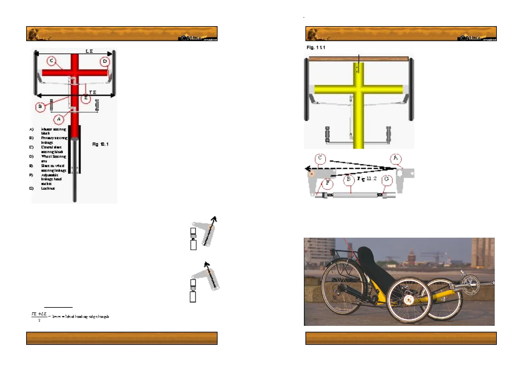
You will now need to use the wooden
beam or string length you just cut and
prepared. Remove the pedal boom
from the frame, as you will need to
use the cut in the bottom of the frame
where the boom fastening bolts are
to align the wheels precisely, using
the half way mark you made on your
balancing beam or string. Hold the
alignment beam or string perfectly
horizontal with it’s center point at
the groove (see g. 11.1) Using this
groove as a guide, align each wheel
individually by undoing one end of the
steering linkage bar, undoing the safety
locknut on the free end and moving the
end socket in or out by twisting it on
its thread. Align the wheel by replacing
the socket in the wheel’s steering plate
to check whether the center point lines
up with the frame when in contact with the inner surface of the rim. Once you have aligned
both wheels, check that the handlebar is still pointing straight ahead. The alignment beam or
string should now just touch both rims, when it’s center point is at the groove in the frame, as
seen in g. 11.1.