Do you have a question about the Optoma DW318 and is the answer not in the manual?
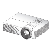
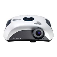
Provides a summary of key features and specifications of the projector.
Details the computer resolutions and sync frequencies supported by the projector.
Lists necessary tools and an overview of the projector for disassembly.
Step-by-step guide to removing the projector's lamp cover.
Instructions for removing the projector's lamp module.
Procedure for removing the projector's top cover.
Guide on how to detach the keypad board.
Instructions for removing the zoom ring assembly.
Steps to remove the internal top shielding.
Procedure for removing the main logic board.
Guide to removing the shielding for the main board.
Instructions for removing front cover and IR sensor.
Procedure for removing the projector's engine assembly.
Steps for removing the color wheel assembly.
Guide to removing the DMD chip and board.
Instructions for removing the rod module.
Procedure for detaching the focus ring.
Steps for removing the cooling fan assembly.
Guide to removing the Low Voltage Power Supply module.
Instructions for removing the I/O cover and security bar.
Procedure for removing the interlock switch.
Instructions for removing the lamp driver module.
Steps for removing the projector's bottom shielding.
Guide to removing the internal speaker.
Procedure for adjusting the rod for image alignment.
Instructions to reset or update the lamp usage counter.
Interprets LED status indicators for diagnosing issues.
Step-by-step guide for addressing common projector symptoms.
Lists the hardware and software required for testing.
Procedure to access and use the projector's service mode.
Instructions to reset On-Screen Display settings to defaults.
Specifies the environmental and screen conditions for testing.
Details the steps for inspecting projector performance after repairs.
Procedure for testing projector functionality using a PC connection.
Test procedure to check for unwanted light leakage.
Test procedure for identifying bright pixel defects.
Test procedure for identifying dark pixel defects.
Test procedure for checking bright blemishes on the display.
Test procedure for checking dark blemishes on the display.
Procedure to visually inspect and verify image focus.
Test procedure to evaluate color accuracy and saturation.
Tests for evaluating video signal quality across different inputs.
Procedure for testing the projector's audio output functionality.
Procedure for testing video and audio performance via HDMI.
Procedure for testing the projector's 3D display capabilities.
Procedures for measuring optical performance metrics like brightness and uniformity.
Includes general function checks and exterior condition evaluation.
Section detailing the process for upgrading the main system firmware.
Lists the software and hardware required for firmware upgrades.
Step-by-step guide to install the DLP Composer Lite software.
Instructions for performing a firmware upgrade using DLP Composer Lite.
Section detailing the process for upgrading the 8051 microcontroller firmware.
Lists the software and hardware required for 8051 firmware upgrades.
Step-by-step guide to install the NLINK software.
Instructions for installing the necessary USB drivers.
Instructions for performing an 8051 firmware upgrade using NLINK.
Explains Extended Display Identification Data and its purpose.
Lists software and hardware required for EDID operations.
Steps for setting up the EDID programming fixture and connections.
Procedure for inputting and programming EDID data.
Explanation of the coding system used for Printed Circuit Board Assemblies.
| Number of colors | 16.78 million colors |
|---|---|
| Projection distance | 1.2 - 12 m |
| Vertical scan range | 25 - 85 Hz |
| Horizontal scan range | 15.3 - 91.1 kHz |
| Projection technology | DLP |
| Contrast ratio (typical) | 2500:1 |
| Screen size compatibility | 32.77 - 359.44 \ |
| Projector native resolution | WXGA (1280x800) |
| Keystone correction, vertical | 40 ° |
| Resolution | 1600 x 1200 pixels |
| Aspect ratio | 16:10 |
| RS-232 ports | 1 |
| Network ready | No |
| Dimensions (WxDxH) | 286 x 192 x 84 mm |
| Power requirements | 100 - 240V, 50 - 60Hz |
| Connectivity technology | Wired |
| Throw ratio | 1.55 - 1.7:1 |
| Focal length range | 21.86 - 24 mm |
| Lamp power | 185 W |
| Light source type | Lamp |
| Service life of light source | 3000 h |
| Service life of light source (economic mode) | 4000 h |
| HD-Ready | Yes |
| RMS rated power | 2 W |
| Serial interface type | RS-232 |
| USB 2.0 ports quantity | USB 2.0 ports have a data transmission speed of 480 Mbps, and are backwards compatible with USB 1.1 ports. You can connect all kinds of peripheral devices to them. |
| Component video (YPbPr/YCbCr) in | 0 |
| Noise level | 30 dB |
| Power consumption (standby) | 233 W |
| Power consumption (typical) | 207 W |
| Operating temperature (T-T) | 5 - 40 °C |
| Operating relative humidity (H-H) | 10 - 80 % |
| Market positioning | Portable |
| Weight | 2300 g |
|---|