12
Connection
6.8 Connection diagram
The gure shows an example when an external potentiometer is connected.
External potentiometer
PAVR2-20K
(sold separately)
21
3
0 to 20 kΩ
+
CN1
Motor connector
CN3
CN4
–
24 VDC±10%
DC power supply
Connecting the USB
DIN0 (START/STOP)
14
CN2
13
12
11
10
9
8
DIN1 (RUN/BRAKE)
DIN2 (FWD/REV)
DIN3 (M0)
DIN4 (M1)
DIN5 (ALM-RST)
VH
7
VM
6
VL
5
GND
DOUT0 (SPEED-OUT)
DOUT1 (ALM-B)
DOUT2 (TLC)
DOUT3 (DIR)
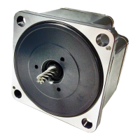
Connecting the motor
Motor
4
3
2
1
Connecting output signals
Connecting input signals
–
+
o external
e
Note
Insulate unused lead wires which are on the opposite side to the connector of the I/O signal cable to prevent them
from contacting other devices, or connect them to 5 VDC or the signal ground (GND) of your external control device
according to usage of signals.
p.10

 Loading...


