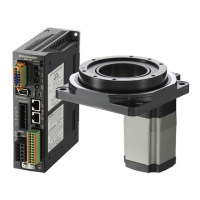
Connection
−16−
•
Connection example for I/O signals
This is a connection example for when the product is operated using relays, switches and other contact switches with
the sink logic setting.
If the product is operated or stopped using a programmable controller, refer to p.17 for when using with the source logic
setting.
Pin No.2 0 V (GND)
Pin No.1 +24 V
Pin No.3 IN0 [FWD]
Pin No.4 IN1 [REV]
Pin No.5 IN2 [M0]
Pin No.6 IN3 [M1]
Pin No.7 IN4 [ALARM-RESET]
Pin No.8 IN5 [FREE]
24 VDC±10%
150 mA or more
R
0∗
R
0∗
Pin No.13 OUT0+ [SPEED-OUT]
Pin No.14 OUT0− [SPEED-OUT]
Pin No.15 OUT1+ [ALARM-OUT]
Pin No.16 OUT1− [ALARM-OUT]
4.5 to 30 VDC
40 mA or less
∗ Recommended resistance value for when the limiting resistor R
0
is connected
24 VDC: 680 Ω to 4.7 kΩ (2 W)
5 VDC: 150 Ω to 1 kΩ (0.5 W)
Connect a current-limiting resistor R
0
according to the power supply voltage so that the current owing
through the output signal will not exceed 40 mA.
Internal circuit conguration of signal input part
All input signals of the speed controller are photocoupler inputs.
0 V
+24 V
Pin No.
3 to 8
2
4.7 k
Ω
SW1
SINK
SOURCE
Internal circuit conguration of signal output part
All output signals of the speed controller are photocoupler/
open-collector output.
The ON voltage of the output circuit is 1.6 VDC maximum.
When driving each element using the output signal circuit, give
consideration to this ON voltage.
External power supply: 4.5 to 30 VDC, 40 mA or less
14, 16
13, 15
Pin No.
Note
•
Always connect a current-limiting resistor. If the external power supply is connected to the
output circuit directly without connecting a current-limiting resistor, the speed controller will be
damaged.
•
When connecting a relay (inductive load), etc., to detect
alarm outputs, use a relay with built-in ywheel diode,
or provide a y-back voltage control measure based on
diode, etc., for the inductive load.
CN4
Pin No.13, 15
Inductive load
Flywheel diode
Using external control equipment with a built-in clamp diode
If external control equipment with a built-in clamp diode is
used, a leakage path may form and cause the motor to operate
even when the external control equipment power is off, as
long as the speed controller power is on.
Since the power capacity of the external control equipment
is different from that of the speed controller, the motor may
operate when the external control equipment and speed
controller powers are turned on or off simultaneously.
When powering down, turn off the speed controller power
rst, followed by the external control equipment power.
When powering up, turn on the external control equipment
power rst, followed by the speed controller power.
equipment
Speed controller
VCC
+24 V
0 V
0 V
Clamp
diode
CN4
Pin No.3 to 8
Pin No.2
 Loading...