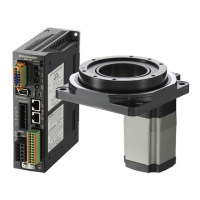
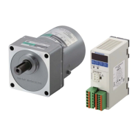
Function
−31−
Description of I/O signals which can be assigned
6 input signals and 2 output signals out of the following signals can be assigned.
Signal Terminal Signal name Description
Input
IN0
IN1
IN2
IN3
IN4
IN5
FWD
When the FWD input is turned ON, the motor output shaft rotates in the
forward direction based on the set acceleration time. When the REV input is
turned ON, the motor output shaft rotates in the reverse direction. When the
input is turned OFF, the motor will stop based on the set deceleration time.
If both the FWD input and REV input are turned ON, the motor stops
instantaneously.
(The rotation direction can be changed with the parameter setting.)
REV
M0
These signals are used to select the operation data.
The operation data which is executed can be selected from 4 operation data
in a combination of these signals.
M1
ALARM-RESET
This signal is used to reset the present alarm generated by which the
protective function of the speed controller was activated.
Be sure to remove the cause of the alarm before turning the ALARM-RESET
input ON. Refer to p.33 for the resetting methods and timing chart.
FREE
If the FREE input is turned ON while the motor is operated, the motor will
coast to a stop.
While the FREE input is being ON, the motor will not rotate even if the FWD
input or REV input is turned ON.
EXT-ERROR
When turning this signal OFF, an alarm generates and the motor stops.
Then "
AL6E
" will be shown on the display (normally closed).
Output
OUT0
OUT1
SPEED-OUT
12 pulses are output with each revolution of the motor output shaft
synchronously with the motor operation.
The motor rotation speed can be calculated by checking the SPEED-OUT
output frequency.
SPEED-OUT output frequency =
1
T
Motor rotation speed
[r/min]
SPEED-OUT output frequency [Hz]
12
× 60
T
output waveform
=
ALARM-OUT This signal will be turned OFF when an alarm generates (normally closed).
TH-OUT
When the built-in overheat protection device (thermal protector) of the
motor is activated (OPEN), this output signal will be turned ON. If the motor
temperature drops and the thermal protector is closed, this output signal will
be turned OFF. (It is enabled while the AC power is input.)
WNG
This signal is output when a warning generates.
When the warning is released, it will automatically turn OFF.
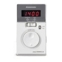
7.6 Prohibiting data editing
This is a function to prevent the set data from editing or clearing by mistake.
Operation data (rotation speed etc.) and parameters cannot be changed while the edit lock function is enabled.
•
Setting of the edit lock function
Press for minimum 5 seconds on the top screen.
The "LK" is displayed and the edit lock function will be enabled.
L F
•
Resetting of the edit lock function
Press for minimum 5 seconds on the top screen.
The "UnLK" is displayed and the edit lock function will be released.
U n L F
•
Display for when the edit lock function is enabled
If the setting value of the operation data or parameter is tried to change while the edit lock function is enabled, "
LF
"
is displayed for about one second.
 Loading...