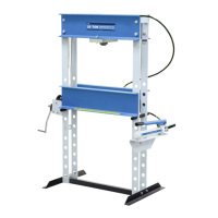
Assembly
Note: Refer to Parts list No. 100551 for location of item numbers referenced below.
Important: During the assembly of the press, hand tighten all nuts and bolts, unless directed otherwise. Once
assembly is complete, use a wrench to tighten all hardware.
1. Place the lower bolster (Item 12, sheet 1 of 2) on two wood blocks (4x4s
approximately 24 in. long). Place blocks perpendicular to the bolster.
IMPORTANT: Make sure the cable attachment holes in the bolster
plates are facing up. See Figure 1, to the right.
2. Attach a foot angle (13) to each press upright (10 and 23) using cap
screws (20), washers (19), and hex nuts (8).
3. Attach the spacer angle (14) to the right-hand press upright (10) with a
cap screw (20).
4. Slide the upright into the end of the bolster assembly (12) until the upright
is tight against the bolster plate.
5. Slide the left-hand press upright (23) into the other end of the bolster
assembly (12) until it is tight against the bolster plate. Then attach the
upright to the angle spacer with a cap screw (20).
6. Mount one of the upper bolsters (1) to the top of each upright (10 and
23) using cap screws (7) and hex nuts (5). The holes for the cylinder
mounting plate (11) must be facing down.
7. Install two pulley axles (4) and pulleys (3). The axles each pass through
the exposed uppermost mounting hole in their respective upright (10
and 23). Before pushing each axle all the way through to the opposite
mounting hole, slide a pulley (3) onto each axle. Note: Once assembly
of the press is complete, lubricate both axles using a general purpose
grease.
8. Mount the remaining upper bolster to the uprights using cap screws (7) and hex nuts (5).
9. Assemble a cap screw (2), two washers (24), and a nut (22) to the pulley bracket located at the top of the left-hand
upright. To allow the cable to be installed later on, only hand thread the nut onto the screw a few turns at this time.
10. Attach the winch assembly (21) to the mounting plate on the left upright using cap screws (18) and hex nuts (22).
Wrench tighten the mounting hardware.
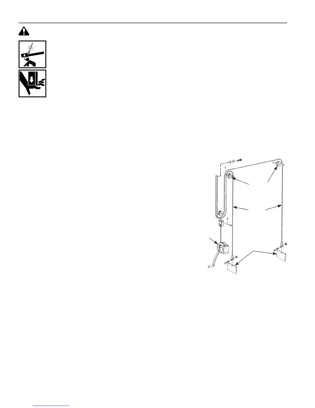
11. Attach one end of the cable (7, sheet 2 of 2, back) to the bolster plate on the right end of the lower bolster (12) using
a cap screw (2, sheet 2 of 2, back) and lock nut (1, sheet 2 of 2, back). Feed the other end of the cable through the
pulley (3) and attach it to the left end of the lower bolster. Finish routing the cable as detailed in Figure 1 above.
IMPORTANT: When looping the cable over the cap screw (2) installed earlier on the pulley bracket, make
sure the cable is between the two washers (24).
12. Operate the winch handle to tension the cable and to lift the bolster assembly off the support blocks. Remove blocks.
13. Insert a pair of bolster pins (15) in the uprights using corresponding holes across from each other.
14. Level the lower bolster by hand.
15. Tighten the cap screw (2) and nut (22) on the pulley bracket to secure the cable between the two washers (24).
WARNING (cont’d)
• To prevent accidental cable breakage, never raise or lower the bolster if a load has been placed on it.
• When lowering the bolster, remove the work piece. Place one support pin all the way through each
front and the back upright in the highest hole under the bolster that will not interfere with the new
bolster position. Remove your hands from the support pins after the pins are in place.
• When raising the bolster, remove the work piece. Leave the support pins in place until the bolster is
raised to its new position. Remove your hands from the support pins after the pins are in place.
• Inspect the entire length of the lifting cables at least every three months, and replace cables that
appear frayed, worn, or crushed. The cables must run on the pulleys easily and the pulleys must be
free to turn. Correct cable maintenance helps prevent cable breakage.
CABLE ROUTING DIAGRAM
Pulley
Assemblies
Press
Cable
Bolster
Plates
Winch
Assembly
FIGURE 1
Assembly & Operating Instructions
 Loading...