Do you have a question about the Oxford Instrucments ITC503 and is the answer not in the manual?
Ensuring proper electrical ground connection for shock hazard minimization.
Guidelines for safe disconnection and discharge before repair or fuse replacement.
Guidance on navigating the manual for operating and service information.
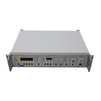
Overview of the ITC503's features, applications, and hardware.
Instructions for setting the voltage selector and fuses.
Details on connecting sensors and heaters via the 9-way D-socket.
Pinout and configuration for RS232 serial communication.
Information on connecting multiple instruments via RS232.
Details on connecting and using the GPIB interface.
Using ITC503 as a gateway to link non-GPIB instruments.
Overview of the auxiliary port's functions and connections.
Description of the pseudo-analogue output for trend monitoring.
Details on controlling multiple heaters with the optional board.
Explanation of Room Temperature (RT) reference for thermocouples.
Using the ITC503's onboard RT sensor for thermocouple compensation.
Using Channel 1's RT sensor for compensation on other channels.
Description of POWER, ADJUST, and CONTROL buttons.
Step-by-step guide for initial instrument power-up and self-test.
How to select input sensors for display and automatic control.
Procedure for adjusting the set point using front panel controls.
How to manually adjust heater output voltage.
How to engage automatic heater control and monitor output.
Setting Proportional, Integral, and Derivative control parameters.
Using the AUTO-PID feature for automatic control parameter selection.
Operation of automatic and manual gas flow control.
Using the gas flow control for cryocooler operation.
Connecting and using the OP3KW MkII high power output unit.
Accessing and using the instrument's test and configuration modes.
Setting an upper limit for the heater output voltage.
Setting temperature limits for individual sensors.
Setting an additional limit on the desired temperature.
Using external over-temperature limits via the auxiliary socket.
Adjusting display decimal places for resolution control.
Procedure for saving limits and other settings to non-volatile memory.
Method to temporarily disable sensor temperature limits.
Using the sweep facility to program temperature profiles.
Procedure to initiate a programmed temperature sweep.
Indications of sweep status via lamps and display.
How to terminate a sweep program before completion.
Entering and setting parameters for a sweep program.
Saving programmed sweep sequences to memory.
Calibrating the instrument to specific sensor characteristics.
Retaining calibration settings after power down.
Configuring parameters for gas flow and cryocooler operation.
Setting up automatic PID parameter tables.
Configuring the instrument's GPIB address.
Overview of remote control via RS232 or GPIB interfaces.
Details of RS232 and GPIB hardware communication protocols.
Format and structure of commands and instrument responses.
Convention for handling signed decimal numbers in communication.
Operating instruments in parallel via the ISOBUS system.
Detailed explanation of GPIB interface functions and usage.
Explanation of user-level commands like C, Q, R, U, V, W, X.
Details on commands for engineering and software interface.
Overview of configuring sensor input channels for specific sensors.
Procedure for accessing input board switches and data tables.
Setting DIP switches for correct input stage hardware configuration.
Selecting the correct software data table for sensor linearisation.
Background information on designing custom sensor ranges.
Classification and characteristics of different sensor types.
Determining input stage configuration and switch settings.
Setting sensor energisation current for resistance thermometers and diodes.
Empirically setting span and zero switches for sensor ranges.
Process for calculating and loading linearisation data.
How the input signal is amplified and converted to frequency.
Theory behind ZERO and SPAN adjustments for sensor input.
How sensor characteristics are mapped using straight line segments.
Criteria for good control: accuracy, stability, and response.
Description of control without feedback, using manual power adjustment.
Explanation of simple on/off temperature control.
Theory of proportional control varying output based on error.
How integral action removes residual error and prevents oscillation.
Use of derivative action to reduce overshoot and improve response.
Alternative terms used for 3-term control in North America.
Principles behind the ITC503's motorized needle valve control.
Explanation of the ITC503's internal circuitry and power supply.
Using test modes for hardware testing and configuration.
Features and general operation of the capacitance sensor input board.
Wiring details for connecting sensors and shields to the ITC503.
Procedure for using the capacitance sensor as a transfer standard.
Calibrating the capacitance sensor for 'Lin' or temperature display ranges.
Detailed explanation of the capacitance sensor input circuitry.
| Brand | Oxford Instrucments |
|---|---|
| Model | ITC503 |
| Category | Controller |
| Language | English |