17474v4.0 5
One-Touch™ Test Mode
To speed up installation and testing, One-Touch™ testing is provided which allows the controller
functionality to be tested at the controller or reader.
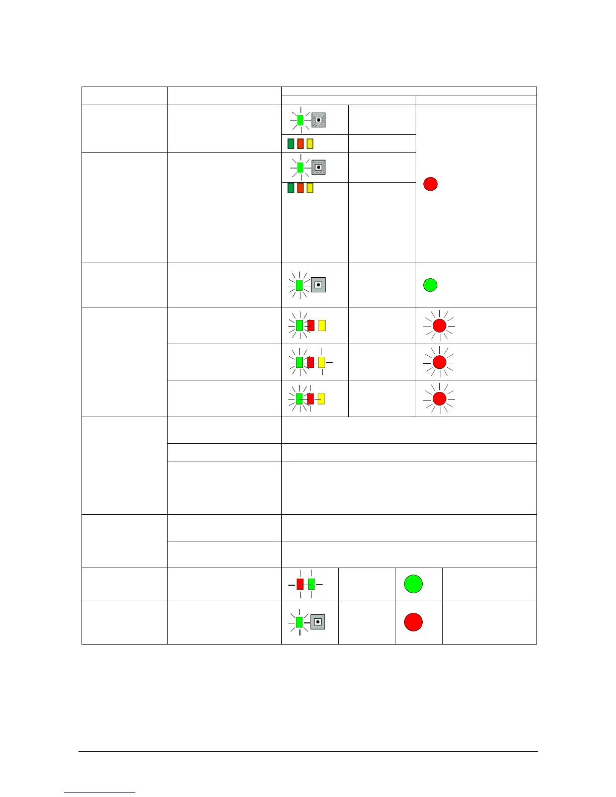
Observation
Test Action
Controller Reader
The green system
status LED flashes
at normal rate.
Normal Operation
Door status LEDs
off.
The green system
status LED flashes
at normal rate.
One-Touch™ View
Mode
Hold down the One-Touch™
button for less than 2 seconds.
Present keys and press RTE
switches and observe LEDs.
Automatically exits after 2 minutes
Green on -valid key
has been
presented to
reader
Green flash -
invalid key has
been presented to
reader
Red on - door open
Yellow on - RTE
switch has been
pressed
The normal operation
of the reader.
One-Touch™ Active
Mode
Hold down the One-Touch™
button for 2 to 4 seconds.
The green system
status LED flashes
faster than normal.
The normal operation
of the reader LED
changes, e.g. if
default is red, it turns
green.
Present a key to each reader (the
lock will activate).
The door green
LED flashes once
for SIGA, twice for
SIGB.
The reader LED
flashes once for
SIGA, twice for SIGB.
Press the Request to Exit switch
(the lock will activate).
The door green
LED flashes three
times and the
yellow LED is lit.
The reader LED
flashes three times.
Reader and Request to
Exit Test
Open the door contact.
The door green
LED flashes four
times and the red
LED is lit.
The reader LED
flashes four times.
Present a key to a reader, press the
Request to Exit switch and open
the door contact simultaneously.
The appropriate auxiliary relay is activated.
Remove link to 0V on tamper or
open circuit tamper switch.
Both auxiliary relay is activated.
Auxiliary and Lock
Relays Test
Remove link to 0V on emergency
override or leave open circuit
tamper switch.
The auxiliary relay is activated.
Remove the link between TAMP
and 0V on the Tamper & Override
terminal block.
The auxiliary relay is activated but the door relays are uneffected.
Tamper and Override
Test
Remove the link between OVRD
and 0V on the Tamper & Override
terminal block.
Both auxiliary and lock relays are activated, the door opens and the lock operates.
RS-232 Test
(PAC 512 only)
Link Tx and Rx on the RS-232
terminal block.
The red and
green RS-232
LEDs are lit.
There is no effect at the
reader.
Leave One-Touch™
Active Test mode
Hold down the One-Touch™
button for less than 2 seconds.
One-Touch™ Test mode will
automatically be timed out after 1
hour and on power down and up.
The green
system status
LED returns to
its normal flash
rate.
The reader LED returns to
its normal operation.
 Loading...