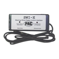
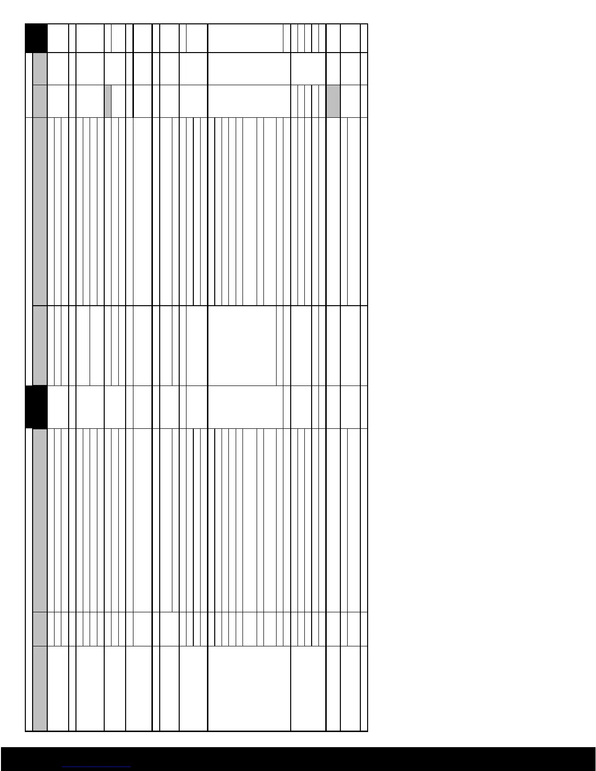
Vehicle
Interface Wire
Vehicle Wire Cut Loops
Version
Make(s) Year(s) Model(s) Color Connector Pin# and wire color Identification (if available) Violet? Brown? Number
To Be Used (see diagrams on page 5)
Acura / Honda 2000-2004 S2000
White
J
Pin 3 - see Note 4 (below)
No
No
3
2003-2004 Accord
J
Pin 3 - see Note 7 (below)
All All except S2000 I or J
If I: Pin 12 (White/Blue) If J: Pin 3 (Green/Red)
Audi 2000 A6 Orange
K Pin 11 (White/Yellow) No No 7
BMW / MINI 1997-1999 All
Yellow
L
Pin 7 or see note 5
No
No
5
2000-2001 All BMW
Pin 7 - see Note 5 (below) and Appendix A (page 5)
2002-2003 All BMW
At steering column
see Note 5 (below)
2003-2004 MINI Cooper S
White/Red/Yellow Dots - see Note 2 (below)
Jaguar 1999 XJR / XK8
White
20-pin plug behind radio
Violet/Yellow - see Note 6 (below)
Yes
No
9
2000-2001 S Type 17-pin plug behind radio White/Black
No
3
2002 X Type Plug behind radio
Pin 19 (Lt. Blue/Yellow) - see Note 7 (below)
KIA 2003 Sorento White
B Pin A6 (Red/Yellow) (Also connect Pin A7 (Black) to ground) No No 9
2004 Amanti
White
12 pin or 3 pin connector
12 pin plug - Pin12 (Black/Orange) (Also connect Pin 6 (brown) to ground) 3pin
plug - Pin3 (Brown/Orange) (Also connect Pin2 (purple) to ground)
No No
8
Lexus 2004 LX / GX / RX330 White R
see Note 10 (below)
No No
8
Mazda
All
All
White
M or N
If M: Pin 8 If N: Pin 9 (Gray / Blk) (Also connect Pin 10 (White / Green) to
ground)
No No
3
Millenia
N Pin 10 (Gray)
Mitsubishi 2002-2003 Eclipse White 8-pin plug behind radio Green/Orange (Also connect Green/Black to ground)
No No
8
2001-2002 Diamante
Yellow
6-pin plug behind radio
Lt. Green/Black
5
1985 Starion / Conquest
Lt. Green/Black (Also connect Lt. Blue/White to ACC +12V, Black to ground)
All-2001 All other models Yellow/ White
Nissan / Infiniti 2002-2003 Maxima / Pathfinder
White
Plug behind radio
a.Blue/Yellow
b.Red c.Brown / White - see Note 8 (below)
No No
3
2002-2004 Altima
a. Green
b.Red/White c.Blue - see Note 8 (below)
2002-2003 QX4
a.Blue/Yellow
b.Grn/Blk or Red c.Brown/White - see Note 8 (below)
2003 G35
a. Green b. Red c. Yellow - see Note 8 (below)
2000-2002 Xterra, Frontier Yellow/Red (Also connect Yellow/Black to ground)
2000-2001 Maxima/Pathfinder
Brown/White, Green/Black, Yellow/Red, Blue/Yellow, Red - see Note 9 (below)
All-2001 All other models except Quest
see Note 9 (below)
All 300ZX
see Note 9 (below). If with cruise control, must leave factory tuner box installed.
1999-2000 Quest
H Pin 14 (White/Black)
1993-95 Quest Yellow F
Pin 2 (Tan, Pink/White, Lt. Blue/Red or Lt. Blue/Black)
5
Land Rover 2002 Freelander
White
Plug behind radio
Black/White (Also connect Black/Red to ground)
No
No
8
1997-1999 Range Rover Pin# 2 Gray/Orange No 9
2000 Range Rover Pin# 2 Gray/Orange (Also connect Pin# 5 Gray/Black to ground) No
9
2003 Range Rover Yellow
At steering column Wht/Gry/yellow dots - see Note 2 (below)
No
5
All All other models White
Plug behind radio
Gray/Red (Also connect Gray/Black to ground) No
8
Saab
1992-2003
9-3, 9-5, 900, 9000
White
22-pin plug above radio at driver
display module
Tap into Black/Yellow
Yes
No
11
Toyota
2003
4Runner / Land Cruiser / Sequoia / Tundra
White R
see Note 10 (below)
No
No
8
2004
4Runner / Land Cruiser / Highlander / RAV4 / Sequoia / Sienna / Solara /
Tundra
see Note 10 (below)
Volkswagen 2001 Jetta / Passat / Golf / GTI Orange
K Pin 11 No No
7
Import Vehicles
Note 1:
If vehicle has rear controls and need to be retained with front controls, connect both pins 13 and
14 to the INTERFACE Green wire, and connect pin 12 (Pink or Violet) to ACC +12V.
Note 2:
Cut the indicated wire. Connect the INTERFACE Green or Yellow wire to the switch side of the
wire. Insulate the radio side.
Note 3:
Verify the wire by checking for +5V at rest; 0-5V when a button is pressed. Cut the wire (except
when noted in above chart). Connect the INTERFACE White wire to the switch side of the wire.
Insulate the radio side.
Note 4:
To connect mute function: Using a 12V SPST or SPDT relay, tap into pin 14 (Blue/Yellow) and
connect to pin 85. Connect pins 86 and 87 to ground. Connect pin 30 to the mute input of the new
head unit. Connect a 3.6k to 4k ohm resistor across the white and black wire of the INTERFACE.
Note 5:
Tracing the wire from pin 7 of radio plug (color may vary), cut the wire at the steering column.
Connect the INTERFACE Yellow wire to the switch side. Insulate the radio side. Colors known:
White/Red/yellow-dots or White/Gray/Yellow-dots. Wait 15 seconds after turning key to accessory
position before going into radio programming.
Note 6:
After cutting the Violet loop, insert a 1500-ohm resistor in-line on the loop.
Note 7:
Jaguar - connect a 4900-ohm resistor (supplied) across the INTERFACE White and Black wires.
Accord - connect a 5400-ohm resistor (supplied) across the INTERFACE White and Black wires,
connect Pin# 11 brown wire to chassis ground.
Note 8:
16 pin plug: Connect the (a.) wire to a 150-ohm resistor and the (b.) wire to a 47-ohm resistor
(both supplied). Connect the free ends of the resistors to the INTERFACE White wire. Connect the
(c.) wire to ground.
Note 9:
Test to locate a separate wire for each button (wires will show close to 0 ohms when button is
pressed). Connect one resistor (supplied) to each wire, starting with the lowest value, then connect
the free ends of the resistors to the INTERFACE White wire. 300ZX rotary volume knob can’t be
interfaced, only the push buttons.
Note 10:
Connect the pin 6 wire to ground. Connect the pin 7 wire to the INTERFACE White wire. Connect
a 150-ohm resistor (supplied) to the pin 8 wire and connect the free end also to the INTERFACE
White wire.
 Loading...