INLINE MOUNT Exhaust Brakes
INSTALLATION MANUAL - L2031
PG. 7
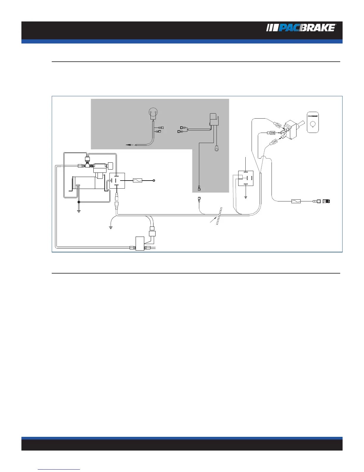
EXHAUST BRAKE WIRING SCHEMATIC
1998-2002 Ford Trucks and Econoline Vans
Equipped With Powerstroke
Ford® Brake Pressure switch
Blk./Yel. Blue
Red
Dash
switch
OFF
Red
Red
Red
Red
To IVS
Ground
Red
Black
15 Amp
Fuse
12V+
Ignition
Switched
Green
Black
Firewall
Blk./Yel.
To Ford® PCM
Blue
Cruise
Relay
Green
NOTE:
SHADED AREA
APPLIES TO
CRUISE
CONTROL
VEHICLES
86
87
85
30
87a
Red
Ground
Relay
Air Intake
Filter
20 Amp
Fuse
Connect to
positive battery
terminal
87
30
87a
85
86
Black
Yellow
Red
Green
To Brake
Green
THROTTLE RELAY INSTALLATION
At the throttle pedal, locate the I.V.S. (Idle Validation Switch).
NOTE: The IVS connection is critical and must be correct. We recommend using a 12 volt test light to verify the cor-
rect wire BEFORE installing the “T” tap.
Most common for vehicles built after 10/2000 is a red wire with a green stripe 2nd from the top of the connector, however because
of possible production changes, using a test light is the only way to be sure. With the ignition on, probe this wire with the test light
first as it should be 12 volt positive with the accelerator pedal to the floor. Release the pedal and the light should go off. If this is
correct connect this wire as explained below, if not, probe the remaining wires until you locate the one which has 12 volts positive
with the accelerator pedal depressed and no current with the pedal released.
With the correct wire selected, use the blue electrical “T” tap supplied and tap into this wire. Plug the insulated male end of the 12”
yellow wire into the “T” tap. Connect the opposite end of the yellow wire to terminal 86 of the supplied relay. Connect the 12” black
wire to terminal 85 of the relay and find a good vehicle ground for the eye terminal on the opposite end.
Connect the two red harness wires to terminals 30 and 87A and then secure the relay to existing wiring (in this location) with the
tystraps provided.
 Loading...