Do you have a question about the Paccar SmartAir eHVAC System and is the answer not in the manual?
Explains key symbols and signal words used for hazard communication.
Details safety measures for working with HFC134a refrigerant and PVE oil.
General safety precautions for performing repairs and work on the unit.
Identification and description of exterior system components.
Identifies and describes the function of fuses in the system.
Identifies and describes the function of relays in the system.
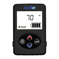
Explains the EHVAC unit's control display for temperature and blower speed.
Describes the device that controls the unit and compressor output voltage.
Module controlling voltage to the evaporator blower for variable speeds.
Sensor monitoring evaporator outlet temperature, preventing freezing.
Blower that circulates conditioned air into the sleeper.
Blower drawing air through the condenser coil for cooling.
Monitors auxiliary batteries and controls the battery separator solenoid.
Connects truck batteries to EHVAC batteries, managing charging.
Identification and description of interior system components.
Switch preventing compressor operation due to high internal pressure.
The hermetically sealed refrigeration system's core unit.
Auto-reset switch protecting the compressor from high temperatures.
Protects the evaporator coil from dust and debris.
Troubleshooting steps for common A/C system issues.
Troubleshooting steps for a non-operational AC unit.
Troubleshooting steps for auxiliary battery charging issues.
Troubleshooting steps for lack of cooling despite unit operation.
Troubleshooting steps for intermittent cooling or cycling issues.
Troubleshooting steps for low airflow when cooling.
Troubleshooting steps for reduced system run time.
Troubleshooting steps for noise or vibration issues.
Troubleshooting steps for the ESPAR heating system.
Troubleshooting steps for a heater not operating when connected.
Troubleshooting steps for a heater not connecting or operating.
Troubleshooting steps when the heater blows cold air instead of heat.
Guidance on checking and maintaining battery health and voltage.
Details on checking the control display and its wake-up signal.
Procedure for testing relays using an OHM meter and checking voltage.
Procedures for testing temperature sensors and control modules.
Procedures for testing condenser fan and evaporator blower motors.
Detailed procedure for testing the BMS and its battery separator function.
Procedures for testing CAN bus communication and Espar heater signals.
Procedures for servicing O-rings, lines, and system units.
Procedure for evacuating the Peterbilt EHVAC System of air and moisture.
Procedure for charging the EHVAC system with R-134a refrigerant.
Specifies the correct refrigerant charge amount for the EHVAC system.
Provides resistance values for testing the discharge sensor.
Detailed schematic of internal wiring for units prior to August 2016.
Schematic illustrating external wiring connections for the EHVAC system.
Schematic of wiring for units manufactured from August 2016 onwards.
Details pin assignments, wire colors, functions, and voltages for the control module.
How to start the system and interpret the initial display.
Procedure for selecting AUTO, COOL, or HEAT modes and setting temperature.
Procedure for adjusting the fan speed settings.
How to view system runtime and access service mode for fault codes.
Notification and reset procedure for the EHVAC filter.
| Brand | Paccar |
|---|---|
| Model | SmartAir eHVAC System |
| Category | Controller |
| Language | English |