Do you have a question about the Pahlen Maxi Heat and is the answer not in the manual?
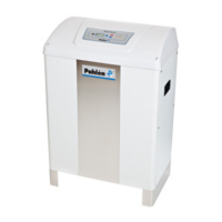
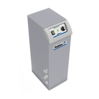
The Pahlén Maxi Heat Digital is a compact and efficient electric heater designed for swimming pools. It features a fiberglass-reinforced polypropylene tank containing either Incoloy 825 or titanium heating elements. Titanium elements are recommended for aggressive or saltwater pools, or when a salt chlorinator is used. An electronic thermostat controls the pool water temperature up to a maximum of 45°C, and four indicator lights show when the heating element is active. The heater is available in various power outputs, ranging from 18 kW to 60 kW for 230V connections, and from 16.2 kW to 78 kW for 380V or 400/415V connections. The specific power and voltage ratings are detailed on the heater's rating plate.
Installation must comply with local regulations, ordinances, and utility company requirements. The heater should not be covered, enclosed, or placed near flammable materials or in direct sunlight. Built-in safety controls include a flow switch and a manual high-limit thermostat to protect against overheating and element burnout. The heater also features integrated automatic fuses. The heating element is controlled by an electronic thermostat to maintain a safe and comfortable pool water temperature. It is crucial not to activate the heater electrically unless it is completely filled with water. The manual emphasizes that "electrical equipment should not be used by children or persons with reduced physical, sensory or mental capabilities, or lack of experience and knowledge, unless they have been given supervision or instruction. Children should not be allowed to play with the appliance" (IEC 60335-1/A2).
Recommended water parameters for optimal heater performance are:
Plumbing work should be completed before electrical installation. The heater should be positioned to allow access to the service hatch (on the side opposite the drain plug) and the top lid. Secure the heater to the foundation using the four Ø13 holes in the base. The recommended water flow through the heater is 170-300 l/min. If flow rates exceed 300 l/min, a bypass should be installed and adjusted to maintain the recommended flow through the heater. To allow for heater maintenance without draining the pool, a check valve should be installed on the outlet pipe after the heater, and a drain valve before the heater inlet. Install unions to facilitate easy removal of the heater for inspection, cleaning, and servicing.
Connect the heater to the pool system as shown in the piping diagram. Only approved valves and fittings should be connected to the outlet. The heater is equipped with G2¼" unions for gluing to PVC pipes with an outer diameter of Ø63 mm. No shut-off valves (install a check valve instead) should be placed between the heater outlet and the pool. To prevent corrosion, chlorine, acid, and other chemicals should be dosed after the heater.
All electrical installations must be performed by a qualified electrician according to the heater's instructions. The heater must be installed with a main power switch. A ground fault circuit interrupter (GFCI) is also recommended. Connect the heater according to the provided wiring diagram (pages 4 and 5). The heater should be installed in such a way that it cannot be activated if the circulation pump is not working (sufficient flow), i.e., the power supply to the contactor must be controlled by the motor protection of the pump. It is critical not to connect the heater to an improper source of electricity. Consult local authorities for specific electrical network parameters. The voltage supplied to the heater should not deviate by more than +5% to -10% from the value specified on the model and rating plate.
The water flow rate can be adjusted using an external bypass valve and a thermometer. The bypass valve is adjusted using the water temperature difference (rise) through the heater as indicated by the thermometer at the heater outlet.
Note that the heater functions only when the circulation pump is running and water is circulating. It will not heat when the filter pump is off or if the temperature control is not calling for heat. In hard water areas, lime can accumulate in the tank and on the heating element. Tank and element should be inspected periodically and scale removed when necessary. If the water in the system stands still for a longer period, drain the heater. Always turn off the heater and disconnect the main fuses before draining the heater. Close both the inlet valve and bypass valve and open the drain plug on the heater. The heater contains about 15 liters of water. If a vacuum occurs, loosen the outlet connection a little to ensure complete drainage of the heater. If the pool system is subject to sub-zero temperatures, turn off the power to the heater and the pump and drain the entire system. Open the drain plug, located on the side of the heater. The system drain valve must be left open until it is time to start up the swimming pool again. When back-washing and cleaning the filter, the power to the heater must be turned off.
The display shows an error code. Contact your installer.
| Brand | Pahlen |
|---|---|
| Model | Maxi Heat |
| Category | Electric Heater |
| Language | English |