7
Palmgren Operating Manual & Parts List 83115
OPERATION (CONTINUED)
• Adjust thrust bearing (Ref. No. 36) at rear of blade by loosening
set screw (Ref. No. 23). Position thrust bearing .002” away from
back of blade. Secure position of thrust bearing by tightening
set screw.
• Replace blade guard and secure in position.
BLADE SELECTION
• Blades vary depending on type of material, size of workpiece
and type of cut that is being performed.
• Characteristics which make blades different are width, thick-
ness and pitch.
BLADE WIDTH
• Width of blade describes distance from tip of a tooth to back of
blade.
• Width of blade will affect rigidity of blade. A wider blade will
wander less and produce a straighter cut.
• Width of blade also limits the smallest radius which can be cut.
A
1
/4” wide blade can cut about a
1
/2” radius.
BLADE THICKNESS
• Blade thickness describes the distance between sides of blade.
A thicker blade has more rigidity and stronger teeth.
• A narrow thick blade would be used to cut curves while a wide
thin blade would be used to make long, straight cuts.
BLADE PITCH
• Pitch describes number of teeth per inch or tooth size. A blade
with more teeth per inch will produce a smoother cut.
• The type of material being cut determines number of teeth
which should be in contact with work.
• For soft metals, the proper blade has between 6 to 12 teeth per
inch.
• When cutting hard metals, where shocking is more detrimental,
use a blade with 12 to 24 teeth per inch.
• For softwoods, the proper blade has 4 to 8 teeth per inch.
• For hardwoods, the proper blade has 8 to 12 teeth per inch.
• There should always be at least three teeth in contact with cut
to avoid shocking blade.
• Blade shocking occurs when pitch is too large and blade tooth
encounters too much material. This can strip teeth from blade.
• Blade manufacturers are prepared to supply information about
blades for specific applications.
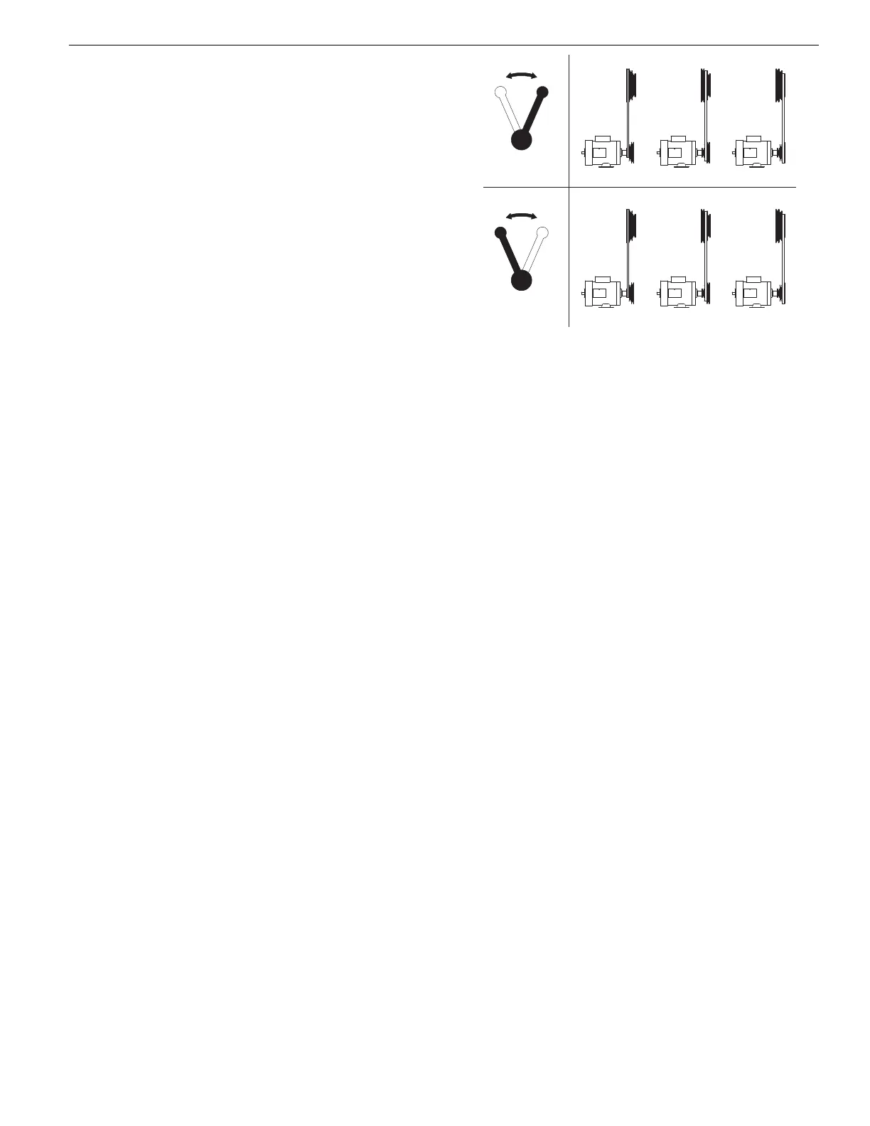
BLADE SPEED
Refer to Figure 6.
• The amount of force with which the blade cuts is determined
by speed.
• High cutting speeds are used on soft materials where less force
is needed and a high rate of material removal is desired.
• Low cutting speeds are used on hard materials when more
force is required.
• To change blade speed, position V-belt in proper configuration
(see Figure 6). Reposition and tension V-belt as described in the
next section.
45 FPM. . . . . . . . . . . . . . . . . . . . . . . . . . . . . . . . . . . . . . . . . . . . . Stainless Steel
65 FPM . . . . . . . . . . . . . . . . . . . . . . . . . . . . . . . . . . . . . . . . . . . . . . . . . . Cast Iron
90 FPM. . . . . . . . . . . . . . . . . . . . . . . . . . . . . . . . . . . . . . Tool Steel, Alloy Steel
110 FPM . . . . . . . . . . . . . . . . . . . . . . . . . . . . . . . . . . . . . . . Hard Brass, Bronze
155 FPM. . . . . . . . . . . . . . . . . . . . . . . . . . . . . . . . . . . . . . . . Soft Brass, Copper
215 FPM . . . . . . . . . . . . . . . . . . . . . . . . . . . . . . . . . . . . . . . . . . . . . . . Aluminum
REPOSITIONING V-BELT (METAL CUTTING)
Refer to Figures 6, 7 and 11(pages 7, 10 and 18).
• Blade speed is determined by the position of the V-belt on the
idler and motor pulleys (Figure 11, Ref. Nos. 38 and 40). Blade
speed is changed by changing pulley position of V-belt.
• Be sure to disconnect saw from power and turn saw OFF before
attempting to change blade speed.
• To change blade speed loosen motor mount plate (Figure 7,
Ref. No. 9) by loosening knob (Figure 7, Ref. No. 14). Position V-
belt on motor and idler pulleys as required. See Figure 6, Blade
Speeds, for recommended pulley and belt settings.
• Tension V-belt by pushing down on motor mount plate and
tightening knob. Belt is properly tensioned when light pressure
applied to midpoint of the belt produces about
1
/2” deflection.
Do not over tighten V-belt.
CHANGING THE SAW OPERATION FROM METAL TO
WOOD CUTTING
Refer to Figures 2, 7, 8 and 11 (pages 4, 10, 12 and 18).
• Remove metal cutting blade. See “Removing Blade”, page 6.
• Remove shroud (Figure 11, Ref. No. 48).
• Loosen knob (Figure 7, Ref. No. 14). Remove V-belt from motor
and idler pulleys (Figure 11, Ref. Nos. 38 and 40).
• Place V-belt on motor and drive pulleys (Figure 8, Ref. Nos. 46
and 50).
• Tension V-belt by pushing down on motor mount plate and
tightening knob. Belt is properly tensioned when light pressure
applied to midpoint of the belt produces about
1
/2” deflection.
• Change clutch handle from “metal” to “wood”. (Refer to Figure 2,
page 4).
• Replace shroud.
• Install wood cutting blade. See “Installing Blade”, page 6.
Properly tension, track and adjust blade guides before
operation.
CHANGING THE SAW OPERATION FROM WOOD TO
METAL CUTTING
Refer to Figures 2, 7, 8 and 11 (pages 4, 10, 12 and 18).
• Remove wood cutting blade. See “Removing Blade”, page 6.
• Loosen knob (Figure 7, Ref. No. 14). Remove V-belt from motor
and drive pulleys (Figure 8, Ref. Nos. 46 and 50).
• Remove shroud (Figure 11, Ref. No. 48).
L H
High Range
LH
Low Range
110 FPM 155 FPM 215 FPM
45 FPM 65 FPM 90 FPM
Figure 6 - Blade Speeds
 Loading...