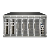
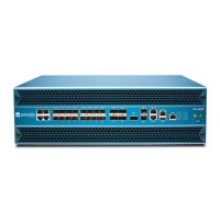
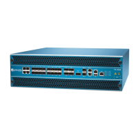
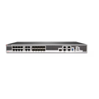
PA-5450
docs.paloaltonetworks.com
1
2
Rack Installation
The PA-5450 firewall ships with the following parts that are required to install the appliance in a 4-Post 19” rack.
Parts List
Part Quantity
Fixed Mounting Bracket, Left 1
Fixed Mounting Bracket, Right 1
Adjustable Mounting Bracket 2
#6-32 x 5/16” Phillips Flathead Screw 16
#8-32 x 3/8” Phillips Panhead Screw 4
1 Refer to Figure 1 to identify the two different mounting bracket types. Slide the adjustable mounting bracket into the “J” shaped lip on
the top edge of the fixed mounting bracket (Figure 2). Repeat for the second fixed mounting bracket.
Before You Begin
Use this document to install and begin setting up your Palo Alto Networks PA-5450 firewall. Refer to the PA-5400 Series Next-
Gen Firewall Hardware Reference at https://docs.paloaltonetworks.com/hardware for safety information, specifications, and
more detailed procedures for installing the firewall.
◼ To ensure safety, two or more people should work together to install the PA-5450 firewall into the rack, preferably using a mechanical
equipment lift.
◼ Verify that the installation site has adequate air circulation and AC or DC power.
◼ Wear the provided ESD strap when installing components or servicing the PA-5450 firewall.
2 Position the bottom edges of the fixed and adjustable brackets to the bottom of the 5 RU rack space reserved for the PA-5450. Align the
slotted holes of the fixed mounting bracket to the holes on the front side of the equipment frame being used. Similarly, align the slotted
holes in the adjustable mounting bracket to the holes on the rear side of the equipment frame.
3 Adjust the brackets to fit the depth of the equipment frame, then secure the brackets to the equipment frame with mounting screws (not
provided) compatible with your equipment frame. Tighten the screws to their recommended torque value.
4 Use the provided 6-32 x 5/16” flathead screws to secure the adjustable bracket to the fixed bracket as shown in Figure 3. A minimum of six
screws are required for each side.
5 Slide the PA-5450 on the brackets that were previously mounted to the equipment frame until the front mounting flanges of the PA-5450
are flush against the mounting surface of the equipment frame. See Figure 4.
6 Secure the PA-5450 to the front of the equipment frame using eight screws (not provided) on each side. See Figure 5. The screws must be
compatible with your equipment frame.
7 Use the four provided 8-32 x 3/8” Phillips panhead screws to secure the rear side of the PA-5450 to the previously mounted brackets. See
Figure 6.
Page 1 of 2
Quick Start Guide
The mounting brackets listed below are designed for equipment frames up to 32” deep.
You may need to loosen the PA-5450 support bracket screws to align the support bracket holes to the threaded holes in the PA-5450
appliance. If adjustment is needed, only loosen the screws on one side at a time.
Adjustable Bracket
Fixed Bracket
“J” Shaped Lip
Fixed 6-32 x 5/16”
flathead screws
Figure 1 Figure 2
Figure 3
Figure 4
Figure 5
Figure 6