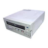
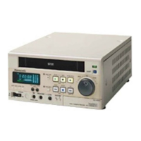
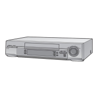
CONTENTS
SPECIFICATIONS
........................................................................................................... Cover
SAFETY
PRECAUTIONS
............................................................................................. 2
SECTION 1
OPERATING
INSTRUCTIONS
...............................................................
1-1
1-1. Front Panel Parts .................................................................................... 1-2
1-2. Rear Panel Parts ..................................................................................... 1-4
1-3.
Setting the Switches ................................................................................ 1-5
1-4.
Search Operations .................................................................................. 1-6
1-5. MEMORY
STOP Functions ........................................................................ 1-7
1-6.
Sensor Recording (AG-7350 only) .............................................................. 1-7
1-7. Timer Recording (AG-7350 only) ................................................................. 1-8
1-8.
Timer
Playback ....................................................................................... 1-9
1-9. Repeat Playback ....................................................................................
1-10
1-10.
Time Code ............................................................................................. 1-10
1-11. ON-SCREEN (Memory Setting) ..................................................................
1-11
1-12. ON-SCREEN (Initial Setting) ..................................................................... 1-12
1-13. Error Displays ........................................................................................ 1-14
1-14.
Troubleshooting
......................................................................................
1-14
1-15.
Controller (Option) ................................................................................... 1-15
1-16. Rack Mount Adaptor (Option) .................................................................... 1-15
1-17. Connector
Signals ................................................................................... 1-16
1-18. Dimensions
............................................................................................
1-16
SECTION 2
DISASSEMBLY
PROCEDURES
..........................................................
2-1
2-1. Disassembly Flow Chart ........................................................................... 2-2
2-2. Detailed Disassembly Method ................................................................... 2-3
2-3.
Screws
.................................................................................................
2-8
SECTION 3
MAINTENANCE
........................................................................................
3-1
3-1. Regular Maintenance ............................................................................... 3-2
3-2. Maintenance Chart .................................................................................. 3-2
3-3. Parts Location ........................................................................................ 3-3
3-4. Maintenance Procedures .......................................................................... 3-4
SECTION
4
MECHANICAL
ADJUSTMENTS
...........................................................
4-1
4-1. Servicing Fixtures & Tools ........................................................................ 4-2
4-2. Tape
Interchangeability Adjustment Procedures ........................................... 4-3
4-3. Other Mechanical Adjustment Procedures ...................................................
4-11
4-4. Assembly and Adjustment Procedures of Mechanism .................................... 4-16
SECTION 5
ELECTRICAL
ADJUSTMENTS
.............................................................
S-1
5-1. Test Equipment ...................................................................................... 5-4
5-2.
Service Information ................................................................................. 5-4
5-3. Adjustment lnformation ............................................................................. 5-5
5-4. Location of Test Point and Controls ............................................................ 5-22
5-5. Circuit Board Layout ................................................................................ 5-25
SECTION 6
BLOCK
DIAGRAMS
.................................................................................
BLK-1
SECTION 7 SCHEMATIC DIAGRAMS AND CIRCUIT BOARDS
..........................
SCM-1
SECTION 8 EXPLODED VIEWS AND REPLACE MENT PARTS LISTS
............
PARTS-1
8-1. Servicing Fixtures & Tools List ................................................................... PARTS-2
8-2. Exploded Views ...................................................................................... PARTS-3
8-3. Mechanical Replacement Parts List ............................................................ PARTS-4
8-4. Electrical Replacement Parts List ............................................................... PARTS-13
- 1 -

 Loading...

