....
I
Q1
1-3. Setting the Switches
1.
2.
3.
4.
I
w:=
==
I
I
J
[I
I
--··----
ca
ca
i!j
[~fl!l
El
....
i~il
-:5~6:·
:5IT6:·
tJt.V
EJ
"~
E1
©©
[!]
0
,.~~ • >
.':",
--::~··
•••
""1{~11
·-·
o
:©;:
:O:·tLQ.
-
l~IJ
l~
ii
~R:ll
:~
""\......T
~
3
2 4
CH2 METER Selector (AG-7350 only)
Used to adjust the audio (CH2) input level during recording. Set
this selector
to
"AUDIO CH2" before making adjustment for the
recording level of audio channel
2.
AUDIO MONITOR Selector
Used to select the audio channel which
is
to be heard
on
the
TV monitor or headphones through the HEADPHONE Jack
on
the front panel or the AUDIO MONITOR OUT connector
on
the
rear panel of the unit.
CH1: To monitor the audio signal from channel1.
MIX: To monitor the mixed audio signals from channels
1 and 2 through the
AUDIO MONITOR OUT
connector or HEADPHONES Jack. When using
headphones. audio channels 1 (left) and 2 (right)
can be monitored separately.
CH2: To monitor the audio signal channel 2.
METER Selector (No LEVEL
meter
for
AG-7150.)
Used to display the recording level of Hi-Fi audio or normal
audio
on
the LEVEL meter and select the audio output signal
from the HEADPHONES Jack
on
the front panel or the AUDIO
MONITOR OUT
connector on the rear panel.
Hi-Fi: Selects Hi-Fi audio.
NORM: Selects normal audio.
AUDIO OUT Selector
Used to select the audio output signal from the NORM/Hi-Fi
audio output connectors
on
the rear panel.
Hi-Fi: Discriminates between Hi-Fi and normal audio
automatically. When there is
no
Hi-Fi audio output
signal, normal audio will be automatically outputted.
NORM: Normal audio is outputted.
CJ
CJ
o
-"~
I
CJ
Cl
~0~
Cl
·o-
1~.
......,.
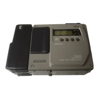
(The above
illustration
is AG-7350.)
'RACKINGn
Aug~~
(§I
CH2
METER
CHlQ
MIX
CH2
E3
1
L
AUDIO
MONITO~
!METoHl
.::.~
1
AUDIO
MONITO~
J
H·f·n
1
NORM~
AUDIO
OUT
I
W:,
1:
I
I
I
I
II
I
v-.'--.,..""
~
ca
i!j
G-t!l
0
.-()
~~11
CQ~~
-:5::6:·
·:5!:6:·
[!]
EJ
[!]
E1
~
......
·~
"'~[
.
-~~l
..
:.. 0
'.©::¢:·:¢:tQ.
~~-~Jl..g~~
.. -
oo~J
.__.
5
6
5.
SENSOR REC Selector (AG-7350 only)
Used
to
select the mode
to
be recorded automatically.
REMOTE: To perform automatic recording of control signal
from the connector at rear panel.
OFF: Normally, set this switch to this position.
VIDEO: To detect the video input signal from the VIDEO
IN
connector and record automatically.
6.
EXT TIMER Selector
Used
to
perform timer recording or playback.
PLAY: To perform timer playback with
an
external timer.
OFF: Normally, set this switch
to
this position.
REC: To perform timer recording with
an
external timer.
7.
MODE LOCK Selector
ON:
OFF:
To operate the unit with a remote controller. When
this switch is set to this position, the operation
buttons
on
the front panel of the unit will be
rendered inoperative.
When this switch is set to this position. the
operation buttons
on
the front panel are operative
and the unit can also be controlled with the remote
controller.
7
CJ CJ
o
I
c;
I
-..TO.
Si
Cl
~1::5'~
Cl
·o-
........
REMOTEEJ
OFF E3
VIDEO
'E•.SC'
AG-7350
I
1
AG-7150
p~;;g
RECt::J
EXTTIMER
1
PLAYn
1
OFF~
EXTTIMER
~ODE
L8CK
OPERATING INSTRUCTIONS
 Loading...