– 13 –
Chapter 1 Overview — Using the camera in a system
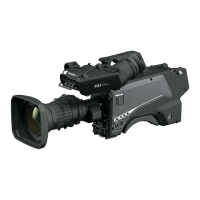
System block diagram
a
b
c
d
e
f
g
h
i
m
j
k
l
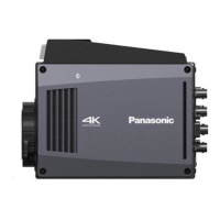
(AK-HC3900G/AK-HC3900GS)
(AK-HCU250P/
AK-HCU250PS/
AK-HCU250E/
AK-HCU250ES)
a: Microphone kit
b: 3.45-inch color viewnder/1.5-inch HD viewnder
c: Handy lens
d: Microphone holder
e: 7-inch LCD color viewnder
f: Master setup unit
g: Camera Control Unit (CCU)
h: Optical ber multi cable
i: ROP cable
j: Remote Operation Panel (ROP)
k: SD memory card
l: Tripod adaptor
m: LAN cable
 Loading...