– 17 –
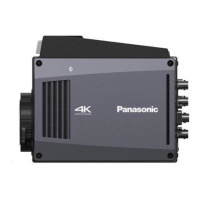
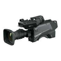
Chapter 2 Description of Parts — Front side
Front side
2
1
4
3
5 76
8
9
10
1 Lens cable/microphone cable clamp
Used for securing the lens and microphone cables.
2 Lens mount (Bayonet type)
This is where the lens is mounted.
3 <SHUTTER> switch
This is the electronic shutter switch.
<OFF>: Disables the electronic shutter.
<ON>: Enables the electronic shutter.
<SEL>: Switches the shutter speed within the preset range.
This switch cannot be used when the CCU or ROP is connected to the camera.
4 <MIC> terminal (front)
Used to connect the microphone (optional).
When using, set the switch on the rear side as follows.
<LINE/MIC/48V> selector switch (<FRONT MIC>): <MIC> or <48V> (when using a phantom microphone)
5 <USER 1> button
A user-selected function can be assigned to this button. Pressing the button performs the assigned function.
6 Tripod mount
Used to attach the tripod adaptor SHAN-TM700 (optional) when mounting the camera on a tripod.
7 <INCOM LEVEL> dial (front)
Adjusts the volume of the intercom receiver.
Set [MAIN MENU] [INTERCOM SETTING] [INTERCOM] [LEVEL VR] [FRONT].
8 Lens lever
After the lens is mounted on the lens mount, this lever can be tightened to secure the lens.
9 <AUTO W/B BAL> switch
<AWB>: Automatically adjusts the white balance. When the white balance is automatically adjusted with the <WHITE BAL> switch on the side of the
camera set to the <A> or <B> position, the white balance is adjusted in several seconds and the adjusted value is stored in the memory.
<ABB>: Automatically adjusts the black balance.
The operation performed when the CCU or ROP is connected to the camera can be set from [MAIN MENU] [SWITCH MODE] [W/B BAL
SETTING].
10 <SELECT> dial button
Turning the <SELECT> dial button while the menu screen is displayed moves the cursor to a setting item. The menu setting can be conrmed by
pressing the <SELECT> dial button.
For details on operations, refer to “Menu operations” (page 35).
 Loading...