– 18 –
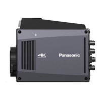
Chapter 2 Description of Parts — Left side
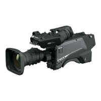
Left side
14
6
7
5
8
15
16
9 10
2
1
4
3
11 12 13
1 <LOCAL> lamp
While this lamp is lit, the ND lter can be adjusted manually.
2 <FILTER LOCAL> switch
This switch sets whether to adjust the ND lter manually or remotely.
3 ND lter selector switch <ND FILTER>
Pressing the <
>/< > buttons switches between the optical lters.
<
> (UP): CLEAR 1/4 1/16 1/64...
<
> (DOWN): CLEAR 1/64 1/16 1/4...
4 ND lter selector LED
The LED for the selected optical lter number lights up.
<1>: CLEAR
<2>: 1/4
<3>: 1/16
<4>: 1/64
5 <GAIN> switch
Switches the gain for the camera image. (<L>, <M>, <H>)
The gain can be congured with the CCU.
This switch cannot be used when the CCU or ROP is connected to the camera.
6 <DISP/MODE CHK> switch
This is a spring switch which can be used to check the shooting status etc.
Push this switch towards <OFF> to hide all displays except for the operation status display of the viewnder, frame display such as an area,
marker, and safety zone.
Push this switch towards <CHK> to display in the viewnder the setting status for shooting functions, and the list of functions assigned to the
<USER 1>/<USER 2>/<USER 3> buttons, etc. Pushing the switch towards <CHK> again while information is being displayed switches the display
to the next information page. The mode check information display disappears after approximately three seconds.
7 <MENU> button
Press this button to display the camera’s [MAIN MENU] screen.
Press the button again to return to the original image.
8 <USER 2> button
A user-selected function can be assigned to this button. Pressing the button performs the assigned function.
9 Busy (active status indicator) lamp
Indicates the active status of the SD memory card and lights up when the card is active.
NOTE
Do not remove or insert the card while this lamp is lit. Doing so may damage the SD memory card.
10 SD memory card slot
This is the insertion slot for the SD memory card (optional).
An SD memory card is used for saving/loading the setting menus of the camera, loading CAC les, updating the software, etc.
For details, refer to “Data” (page 33).
11 <OUTPUT> switch
Switches video output (<CAM>, <BARS>, <TEST>).
This switch cannot be used when the CCU or ROP is connected to the camera.
 Loading...