– 21 –
Chapter 2 Description of Parts — Rear side
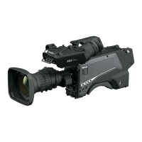
Rear side
8
9
10
11
12
13
14
15
7
16 17
4
3
2
1
6
5
1 <CALL> lamp
Lights up in green when the call switch is pressed from the ROP or CCU.
2 <CALL> switch
While this switch is pressed, the call lamps on the ROP and CCU are lit and the ROP buzzer sounds. (When the ROP buzzer setting is enabled)
NOTE
If the <CALL> switch is pressed when the camera is operating with an external DC power source, the ROP call lamp does not light up.
3 <TALK> switch (<INTERCOM>)
This switch is the <ON>/<OFF>/<PTT> selector switch of the intercom microphone connected to the <INTERCOM> terminal.
Pushes the switch towards <ON>/<PTT> to turn on the microphone.
4 <INTERCOM> terminal
Used to connect the intercom or headset plug.
5 <LINE/MIC/48V> selector switch (<FRONT MIC>)
Used to switch the audio input signal of the audio channel 1.
<LINE>: When connecting audio equipment with the line input
<MIC>: When connecting an external microphone
<48V>: When supplying 48 V power to the microphone
6 <LINE/MIC/48V> selector switch (<MIC 2>)
Used to switch the audio input signal of the audio channel 2.
<LINE>: When connecting audio equipment with the line input
<MIC>: When connecting an external microphone
<48V>: When supplying 48 V power to the microphone
7 Back tally lamp
Lights up when the tally signal is supplied.
R tally signal: Lit in red
G tally signal: Lit in green
R and G tally signals at the same time: Lit in red
8 Back tally lamp selector switch
Used to switch the back tally lamp to on/off.
9 Rear viewnder terminal
Used to connect the 9-inch LCD viewnder AK-HVF100G.
This D-sub connector is used for the viewnder interface.
NOTE
AK-HVF70G, AK-HVF75G can also be connected to this terminal.
10 <OPT> lamp
Indicates the camera’s optical signal reception status.
Normal: Lit in green
Error: Lit in red
NOTE
When an error has occurred, turn off the power of this camera and the CCU, and then clean the optical ber connector. If the error persists,
immediately turn off the power, and contact your dealer.
11 <PGM> dial (<INTERCOM>)
Adjusts the mix level of the intercom and PGM.
 Loading...