177
Aquarea air-to-water heat pumps - Planning and installation manual - 02/2022
Installation
6
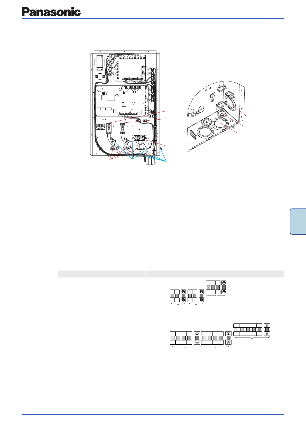
Installation example: Hydrokit WH-SDC12H6E5
4
2
1
3+b
c
a
A
5
6
7
B
A Connection of the power cord
1 RCCB for power supply 1
2 RCCB for power supply 2
3 Cable clamps / strain reliefs
4 Terminal block for indoor / outdoor unit connection
cable
B Detailed view: Cable glands
5 Cable gland for power cord 1 and 2 for indoor / out-
door unit connection cable
6+7 Cable glands for control wiring from optional accesso-
ries
a Use separate cable glands for power cord and acces-
sory cables
b Fix power cord with cable clamps / strain reliefs
c Leave earth conductor longer than the other cables
for safety reasons
Connection diagram – All in One units
Models Connection diagram
WH-ADC0309J3E5(B/C) + WH-UD**JE5(-1)
WH-ADC1216H6E5 + WH-UD**HE5
WH-ADC1216H6E5 + WH-UX**HE5
WH-ADC1216H6E5C + WH-UD**HE5
WH-ADC1216H6E5C + WH-UX**HE5
Terminals on
indoor unit
Terminals on
outdoor unit
Terminals on
disconnector
Indoor / outdoor
unit connection
1 2
1 2
L N
L N
L
1
N
1
L
1
N
1
Power
supply 1
Power
supply 2
WH-ADC0916H9E8 + WH-UD**HE8
WH-ADC0916H9E8 + WH-UX**HE8
WH-ADC0916H9E8 + WH-UQ**HE8
Terminals on
indoor unit
Terminals on
outdoor unit
Terminals on
disconnector
Power supply 1 Power supply 2
A1
A2
A3
L
A1
L
A2
L
A3
N
C1
C2
C3
L
C1
L
C2
L
C3
N
Indoor / outdoor unit connection
For model WH-SHF09F3E8
1
1
2
2
3
3
4
4
5
5
L
L
N
N
L
A1
L
A2
L
A3
N
L
A1
L
A2
L
A3
N
For model WH-SHF12F9E8
1
1
2
2
3
3
4
4
5
5
L
B1
L
B2
L
B3
N
L
B1
L
B2
L
B3
N
L
A1
L
A2
L
A3
N
L
A1
L
A2
L
A3
N
LN
11
N L
N L
22
POWER SUPPLY 2
LB1 LB2 LB3 N
POWER SUPPLY 1
LA1 LA2 LA3 N
45
A
 Loading...