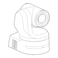
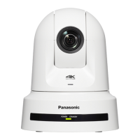
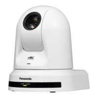
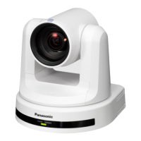
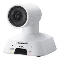
Operating Instructions
Specifications
For details on specifications, visit the Panasonic website (https://pro‑av.panasonic.net/manual/en/index.html) and refer to the Operating Instructions.
Power requirements:
12 V DC
(10.8 V to 13.2 V)
42 V to 57 V DC
(PoE++ power supply)
Current consumption:
5.0 A (XLR connector input)
1.5 A (PoE++ power supply)
indicates safety information.
GENERAL
Ambient operating temperature:
0 °C to 40 °C (32 °F to 104 °F)
Storage temperature:
–20 °C to 50 °C (–4 °F to 122 °F)
Ambient operating humidity:
20% to 90% (no condensation)
Mass: Approx. 4.6 kg (10.12 lb) (excluding mount bracket)
Dimensions (W × H × D):
213.0 mm×277.0 mm×240.0 mm
(8-3/8 inches × 10‑29/32 inches × 9‑7/16 inches)
(excluding protrusions, mount bracket)
Index
Numerics
3G SDI ACTIVE THRU OUT ............................................................... 18
3G SDI OUT connector ....................................................................... 37
12G SDI OUT connector ..................................................................... 36
A
Accessories ......................................................................................... 31
AUDIO IN connector ............................................................................ 37
C
Camera head ....................................................................................... 35
D
DC IN connector .................................................................................. 36
Drop-prevention wire ....................................................................... 9, 35
E
Easy IP Setup Software ....................................................................... 50
EasyIP Setup Tool Plus ....................................................................... 50
External sync signal input format ......................................................... 37
G
G/L IN connector ................................................................................. 37
Ground connector ................................................................................ 37
Grounding ............................................................................................ 27
H
HDMI connector ................................................................................... 36
Hole for securing the camera pedestal ................................................ 35
I
Initial account ....................................................................................... 52
INSTALL POSITION ............................................................................... 7
IP image output 1 ................................................................................ 41
L
LAN connector for IP control ............................................................... 35
M
Mount bracket ......................................................................................... 8
Mount bracket for installation surface .................................................. 35
N
NDI|HX compatible switcher ................................................................ 17
O
Optional accessories ........................................................................... 31
P
Plug-in viewer software ....................................................................... 52
Power .................................................................................................. 53
R
Remote control IDs .............................................................................. 49
RS‑422 connector ................................................................................ 37
S
Service switches .................................................................................. 36
SFP connector ..................................................................................... 36
Status display lamp ............................................................................. 35
T
Tally lamp ............................................................................................ 35
Tilt head ............................................................................................... 35
Tripod screw holes .............................................................................. 38
U
USB3.0 HOST connector .................................................................... 36
V
Ventilation holes .................................................................................. 35
W
WIRELESS ID ................................................................................. 7, 49
Wireless remote control ...................................................... 7, 34, 48, 49
Wireless remote control signal light-sensing area ............................... 35
62 63
 Loading...
