K
kellerevanAug 8, 2025
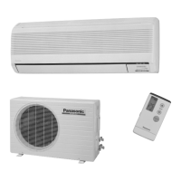
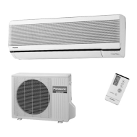
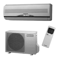
Why is my Panasonic CS-G125KE CU-G125KE Air Conditioner not cooling or heating effectively?
- CCasey RiveraAug 8, 2025
If your Panasonic Air Conditioner isn't cooling or heating effectively, make sure the temperature is set correctly. Also, check if the air filters are dirty and clean them if necessary. Ensure that the air intake or outlet vents are not blocked and that all windows and doors are closed to maintain optimal performance. To check if the unit is working properly, measure the temperature difference between the air intake and outlet vents 15 minutes after starting the operation. For cooling, the difference should be 8°C or above, and for heating, it should be 14°C or above.