1-209
1
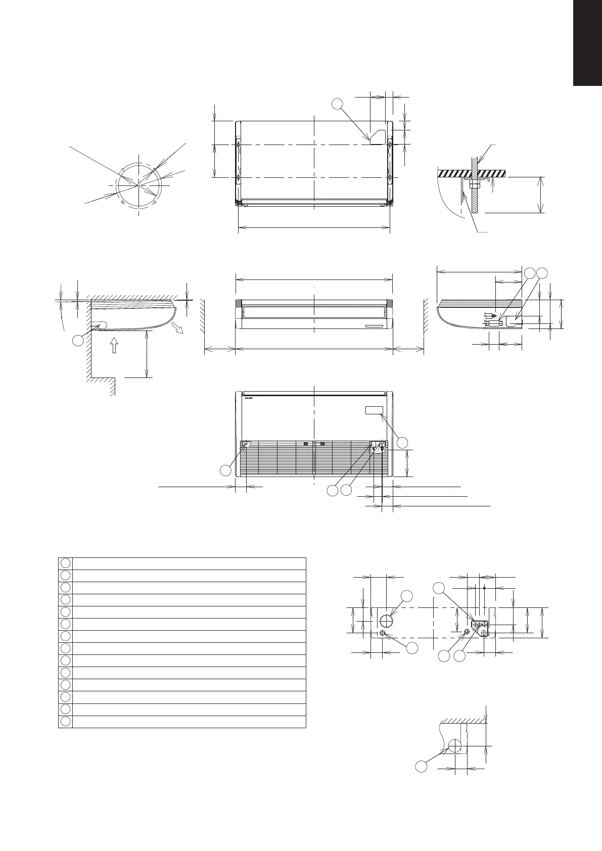
1-2. Dimensional Data
(A) Indoor Units: S-60PT2E5A, S-71PT2E5A
Suspension
bolt
Ceiling
surface
Bracket
Hole position of indoor unit rear-side
(Figure shows view from front)
(Suspension bolt pitch)
1226
Unit
Within
50mm
(Suspension
bolt pitch)
Air intake
Service space
Over
250
Service space
Over
250
Approx. 2°
Air
discharge
Minimum 50cm
90 (Right drain position)
70 (Liquid tubing)
86 (Gas tubing)
(Closed with rubber stopper
at time of shipment.)
(Left drain position)
90
13
5
14
10
11 12
6
131
196
235
185
105
196
176
96
123
8670
97
90
90
120
ø100 (cutout)
ø113
4-ø3.1
1275
1269
7
190265
73114
123 61
18
690
216
18680
131
193
235
9
4
15
4
3
2
216
Tubing hole position on wall surface
(Figure shows view from front)
<Filter size>
(579 x 250 x 16) x 2 pcs.
Distance of each exposed
bolt must be of equal length
within 50mm.
unit :mm
Detailed view of intaking
outside air duct connection port
1 Drain port VP20 (inside diameter ø26mm, drain hose supplied)
2 Left drain position
3 Refrigerant liquid tubing (ø9.52mm, flare connection)
4 Refrigerant gas tubing (ø15.88mm, flare connection)
5 Cover of rear tubing hole
6 Tubing hole on wall surface (ø100mm)
7 Upper side tubing port
8 Right side drain hose outlet port (cutout)
9 Left side drain hose outlet port (cutout)
10
Left-rear side drain hose outlet port (cutout)
11
Power inlet port
12
Remote control wiring and inter-unit wiring inlet port
13
Wireless remote controller receiver installation location
14
Outside air intake duct connection port (ø100mm, cutout)
SM830231-02Single欧州.indb209SM830231-02Single欧州.indb209 2014/09/1913:21:302014/09/1913:21:30
 Loading...