1-210
1
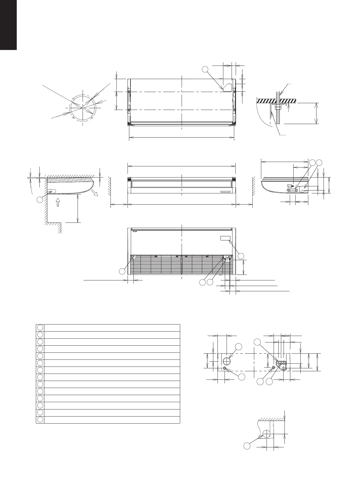
1-2. Dimensional Data
(A) Indoor Units: S-100PT2E5A, S-125PT2E5A, S-140PT2E5A
Suspension
bolt
Ceiling
surface
Bracket
Hole position of indoor unit rear-side
(Figure shows view from front)
Unit
Within
50mm
Air intake
Air
discharge
Minimum 50cm
5
14
10
11 12
6
131
196
235
185
105
196
176
96
123
8670
97
90
90
120
ø100 (cutout)
ø113
4-ø3.1
(Suspension bolt pitch)
1541
(Suspension
bolt pitch)
Approx. 2°
90 (Right drain position)
70 (Liquid tubing)
86 (Gas tubing)
(Closed with rubber stopper
at time of shipment.)
(Left drain position)
90
13
Service space
Over
250
Service space
Over
250
Tubing hole position on wall surface
(Figure shows view from front)
<Filter size>
(736 x 250 x 16) x 2 pcs.
Distance of each exposed
bolt must be of equal length
within 50mm.
unit :mm
Detailed view of intaking
outside air duct connection port
1 Drain port VP20 (inside diameter ø26mm, drain hose supplied)
2 Left drain position
3 Refrigerant liquid tubing (ø9.52mm, flare connection)
4 Refrigerant gas tubing (ø15.88mm, flare connection)
5 Cover of rear tubing hole
6 Tubing hole on wall surface (ø100mm)
7 Upper side tubing port
8 Right side drain hose outlet port (cutout)
9 Left side drain hose outlet port (cutout)
10
Left-rear side drain hose outlet port (cutout)
11
Power inlet port
12
Remote control wiring and inter-unit wiring inlet port
13
Wireless remote controller receiver installation location
14
Outside air intake duct connection port (ø100mm, cutout)
1590
1584
7
190265
73114
123 61
18
235
193
131
80
216
186
690
9
15
4
4
3
2
216
SM830231-02Single欧州.indb210SM830231-02Single欧州.indb210 2014/09/1913:21:302014/09/1913:21:30
 Loading...