1
1-289
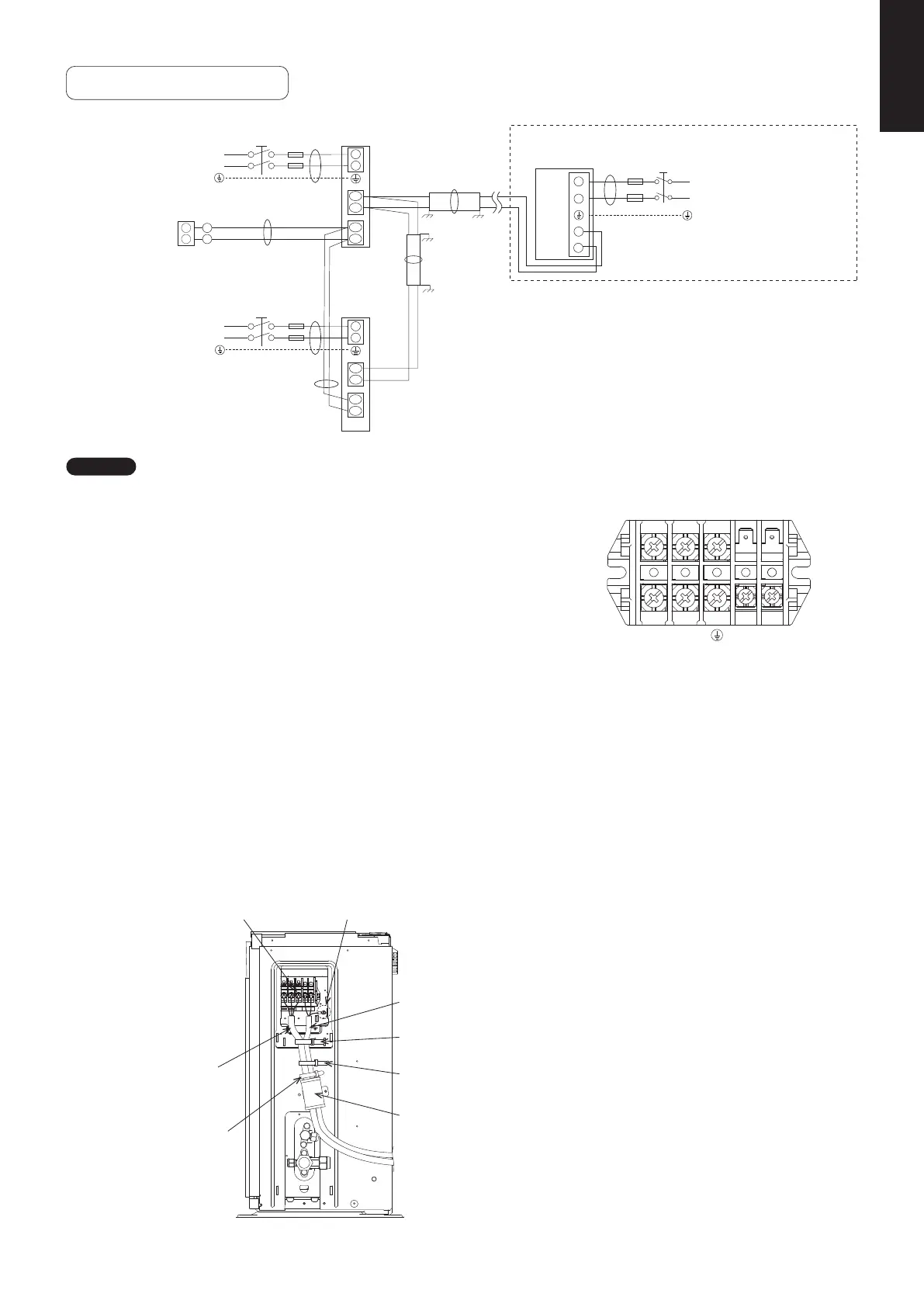
Wiring System Diagrams
U2
R2
U1
R1
R2
R1
L
N
U2
U1
2
1
D
C
B
L
N
L
N
2
1
B
E
C
L
N
A
L
N
2
1
N
L
Power supply
220/230/240 V ~ 50Hz
Power supply
220/230/240 V ~ 50Hz
Ground
Ground
Indoor unit
(No. 2)
Indoor unit
(No. 1)
Ground
Ground
Ground
Ground
Outdoor unit (single-phase)
INV unit
Remote
controller
Power supply
220/230/240 ~ 50/60 Hz
WHT
BLK
NOTE
(1)
Wiring sample
Refer to Section “Recommended Wire Length and Wire
Diameter for Power Supply System” for the explanation
of “A”, “B”, “C”, “D” and “E” in the above diagrams.
(2) The basic connection diagram of the indoor unit shows the
terminal board, so the terminal boards in your equipment
may differ from the diagram.
(3) Refrigerant Circuit (R.C.) address should be set before
turning the power on.
(4) Regarding R.C. address setting, refer to the installation
instructions supplied with the remote controller unit
(Optional).
Auto address setting can be executed by remote controller
automatically.
Refer to the Installation Instructions supplied with the
remote controller (optional).
Outdoor Unit
L1
2
N
Power
supply
Inter-unit
control
wiring
5P terminal board
Earth
Use this screw when connecting
to ground for the unit control line.
Power supply line
Cord clamp
(Field supply)
Unit control line
Cord clamp A
Cord clamp B
Cord clamp C
SM830231-02Single欧州.indb289SM830231-02Single欧州.indb289 2014/09/1913:21:472014/09/1913:21:47
 Loading...