1
1-293
* If multiple indoor units are used, also refer to section “System Control”.
Type U1, T2, F1, N1 and Y2
Caution
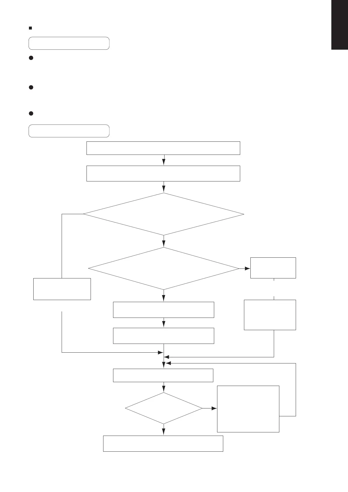
Test Run Procedure
This unit may be used in a single-type refrigerant system where 1 outdoor unit is connected to 1 indoor
unit, and also in a system where 1 outdoor unit is connected to multiple indoor units (maximum 2).
The indoor and outdoor unit control PCB utilizes a semiconductor memory element (EEPROM).
The settings required for operation were made at the time of shipment.
Only the correct combinations of indoor and outdoor units can be used.
This test run section describes primarily the procedure when using the wired remote controller.
YES
YES
YES
NO
NO
NO
Recheck the items to check before the test run.
Check the combination (wiring) of indoor and outdoor units.
See section “System Control”
See section “Items to Check
Before the Test Run”
Is system “single-type”?
(1 indoor unit is connected
to 1 outdoor unit and remote
controller)
Is group control with multiple outdoor units used?
Turn ON the indoor and outdoor power.
Indicate (mark) the combination number.
Automatic
address
setting
Set the remote controller to “test run”.
See section “Test Run Using
the Remote Controller”
See section “Indicating
(marking) the indoor
and outdoor unit
combination number”
Can
operation be
started?
Return the remote controller to normal control.
Turn ON the indoor
and outdoor power.
(Automatic Address Setting)
See section “Setting the outdoor
unit System Address”
Set the outdoor
unit system
address.
Use the remote
controller to
perform automatic
address setting.
Refer to “Table of Self-
Diagnostic Functions”
to check the system.
In addition, refer to
8-8-1 to 5 and correct
any items that need to
be corrected.
Note: Check the indoor-side drainage.
(*1) Required for simultaneous-operation
multi systems and for group control.
(*1)
See section “Automatic address
setting using the remote controller”
SM830231-02Single欧州.indb293SM830231-02Single欧州.indb293 2014/09/1913:21:472014/09/1913:21:47
 Loading...