Getting started
VQT3F57
9
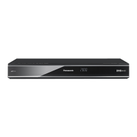
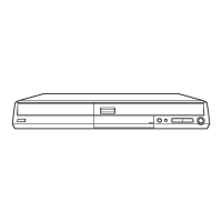
1 Standby/on switch (Í/I) (> 13, 20)
Press to switch the unit from on to standby mode
or vice versa. In standby mode, the unit is still
consuming a small amount of power.
2 Recording indicator
≥The indicator will light up while recording.
≥The indicator will blink while recording is paused.
3 CALL LED
≥The LED will light up when this unit receives
incoming call etc. of the video communication.
(> 61)
4 Remote control signal sensor
–Angle: Approx. 20° up and down, 30° left and
right
–Distance: Within approx. 7 m in front of the unit
5 Start PAUSE LIVE TV (> 26)
6 USB port (> 20)
7 SD card slot (> 20)
8 Channel select (> 22)
9 Display
1 Drive (HDD or SD) indicator
2 SD card slot indicator
3 USB port indicator
4 Copying indicator
5 Remote control signal indicator
6 Main display section indicator
Current time/playback counter, various
messages
7 Playback indicator
8 Timer recording indicator
This indicator lights up when the timer recording
standby is activated.
¾ Rear panel terminals (> 10, 84)
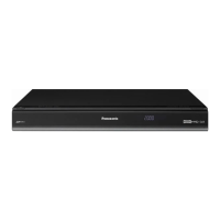
Main unit
Pull to flip down the
front panel.
PLAY
COPY
SD USB
HDDSD
23 4
5
6
7
8
1
DMR-HW100EB-VQT3F57_eng.book 9 ページ 2011年8月5日 金曜日 午後2時4分
 Loading...