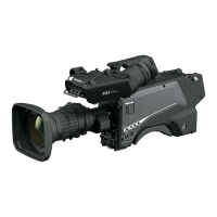
Camera unit
LAN
LINK
ACT
SIGNAL
GND
12 V IN
G/L IN
1 2/PM
3G SDI OUT
SFP+ 12G SDI OUT
USB3.0 HOST
RS-422
SERVICE
1 - AUDIO INPUT - 2
1
2
4
3
6
8
6
9
7
22
11 13 1412
2119
10
5
15
16 17
18 20
7
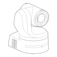
Rear panel
Bottom panel
1. Mount bracket for installation surface (supplied
accessory)
Mount this bracket onto the installation surface, and then attach the
camera main unit to the bracket.
2. Drop‑prevention wire
This wire is screwed down to the bottom panel of the camera main
unit. Loop the circle part of the wire around the hook of the mount
bracket.
3. Status display lamp
This lights in the following way depending on the status of the unit.
Orange Light up When the standby status is established
Blink twice When a signal not matched by the remote control
ID has been received from the wireless remote
control (optional accessory) while the power is on
Blinking
slowly
Firmware being updated (STEP 1: files being
transferred)
Blink three
times
rapidly
When the Identify function (a function that makes
the status display lamp of a specified camera
blink) of EasyIP Setup Tool Plus operates
Green Light up When the power is on
Blink twice When a signal matched by the remote control
ID has been received from the wireless remote
control (optional accessory) while the power is on
Blinking
rapidly
When the initialization process is complete
Red Light up When trouble has occurred in the unit
Blinking
slowly
Firmware being updated (STEP 2: data being
written)
Blinking
rapidly
When a PoE++ software authentication error has
occurred
4. Ventilation holes
Blocking the ventilation holes may cause a malfunction. Make sure
there is sufficient space around the ventilation holes.
5. Tilt head
This rotates in the right and left direction.
6. Wireless remote control signal light‑sensing area
The light-sensing area is provided in three places, on the front panel
of the camera pedestal and at the top of the rear panel.
7. Hole for securing the camera pedestal
This hole is provided in the bottom panel of the camera pedestal.
8. Camera head
This rotates in the up and down direction.
9. Tally lamp
These turn on/turn off with control signals only when the tally lamp
setting is “ON”. The tally lamps light in three different colors; red,
green, and yellow.
10. LAN connector for IP control <LAN LINK/ACT>
This LAN connector (RJ-45) is connected when exercising IP control
over the unit from an external device. Use a LAN cable (category 5e
or above, max STP 100 m (328 ft)) for connection.
Parts and their functions
18
 Loading...