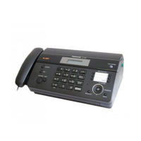
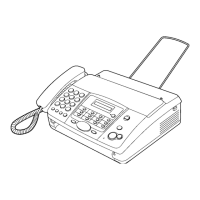
KX-FT21LA
- 68 -
GND
Tester
AC
IC2
IC7
GND
(TEST LAND)
C
B
A
IC1
TEST
D
Item
CLOCK(IC1)
MODEM(IC1)
S-RAM(IC3)
ASIC(IC1)
ALL OK
Check point voltage
Check points
IC1
IC1
IC3 (20 pin), IC1 (6 pin), IC3
RA1~RA4, R10,12, IC1 (104~136 pins)
Please check the soldering and conduction of these
components.
If there is no problem, replace the lCs.
If you still have a problem with the digital board, please see
"checking details". (Refer to page 62.)
BC D
0V 0V 0V
0V 5V 0V
0V 0V 5V
5V 0V 0V
5V 0V 0V
A
5V
0V
0V
5V
0V
Turn off the power supply.
Short using a metallic object, such as tweezers, between the test and GND land, and turn on the AC power.
Check the following voltages by using an oscilloscope or tester.
To cancel the status check mode, turn off the AC power.
This indicates that the Add/Data Bus, RAM, ROM,
MODEM, and ASIC are all completely
connected to the CPU and that control from
the CPU is possible.
To cancel the status check mode, turn off the AC power.
Put the unit in the test mode and check the voltage at lands A, B, C and D.

 Loading...


