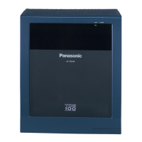
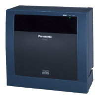
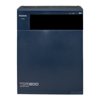
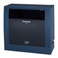
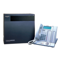
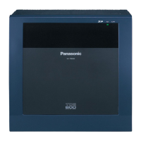
Top Cover
Basic Shelf
Base Shelf
1
2
5
4
3
6
7
8
9
10
11
21
12
13
14
15
16
18
17
19
20
1. Side Panel (Left)
2. Power Unit
3. Fuse
4. Power Indicator
5. Backup Battery Connector
(Connects the Battery Adapter Cable)
6. Power Switch
(Turns ON and OFF the Power of Basic
Shelf)
7. Power Supply Cable
8. Front Panel
9. Transform Cord
10. Base Side Panel (Left)
11. Power Supply Cable Connector
12. Main Power Switch
(Turns ON and OFF the Power of Whole
Unit)
13. Ground Wire Connector (GND)
14. Base Front Panel
15. LED Cable
16. LED Cable Connector
(Connects the LED Cable)
17. Side Panel (Right)
18. Flat Cable Connector
(Connects the Flat Cable from Expansion
Shelf)
19. Cable Opening
20. Base Board
21. Fan Cable

 Loading...


