11 Graphic object
Graphic elements applied in AutoCAD LT and corresponding marking objects
• Depending on the drawing procedures and methods of the DXF data, minor conversion
errors can occur. As a result, some graphics marked by the laser marking system might
differ from the original graphics.
• If you reduce the graphic size, so that it is smaller than the original size, the difference
between the original graphic data and the marked data will increase. In particular for
curved lines, the differences will be more clearly visible.
• If graphic data that contains filling lines cannot properly be converted into marking data,
save the DXF file in a different file format.
• Unsupported elements in a DXF file cannot be marked.
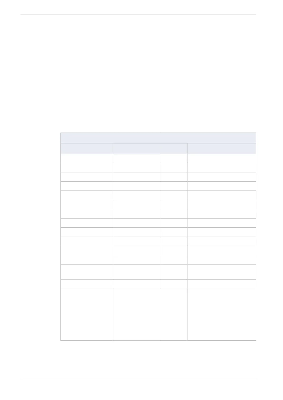
The following tables show which elements are available for the marking process.
· valid (marking is possible)
DXF versions R12J, R13J, R14
Element Graphic name Validity Remark
3DFACE 3D face –
3DLINE 3D line –
ARC Arc ·
ATTDEF Attribute definition –
ATTRIB Attribute –
CIRCLE Circle ·
DIMENSION Dimension –
INSERT Insert graphic ·
LINE Line ·
POINT Point –
2D polyline · Bold line is not supported.POLYLINE
3D polyline –
SEQEND Sequence end · SEQEND in combination with
POLYLINE is available.
SHAPE Shape –
SOLID 2D paint · The SOLID element is converted
into outline and filling lines. The
filling lines are arranged either
horizontally or vertically.
If you set “Adjustment of size
and filling” to “ON” in the object
settings, you can change the filling
lines later.
132 ME-NAVIS2-OP-1
 Loading...