13
Digital Laser Sensor LS-400 SERIES
PRECAUTIONS FOR PROPER USE
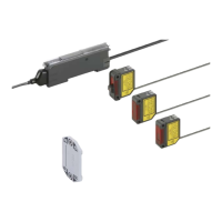
Sensor head
• The tightening torque should be 0.5 N·m or less.
M3 (length 12 mm
0.472 in) screw
with washers
bracket (optional)
• When placing the sensor head horizontally or vertically, the
reector must also be positioned horizontally or vertically as
shown in Fig. 1 below.
If the sensor head is placed horizontally or vertically but the
reector is leaned as shown in Fig. 2 below, the reection
amount will decrease, which may cause unstable detection.
Fig. 1 Proper positioning
When placing the sensor head horizontally or vertically, the
reector shall also be positioned horizontally or vertically.
Fig. 2 Improper positioning
When placing
the sensor head
horizontally or
vertically, but the
reector is leaned.
<Incorrect>
• The lens attachment for line reective type LS-MR1 mounted in
the long sensing range line reective type LS-H22□ is removable.
When LS-H22□ is used without LS-MR1, it will provide the
equivalent performance to the long sensing range spot reective
type LS-H21□. In addition, the optional LS-MR1 can be attached
to LS-H21□ to obtain the performance equivalent to LS-H22□.
• Keep the lens clean of dust, dirt, water, oil, grease, etc.
• Do not apply any excessive force to LS-MR1.
Such force may cause damage.
2
After mounting, check that LS-MR1 is properly xed to
the sensor head.
Removing method
1
Insert a screwdriver into the xing slot located at the top of
sensor head.
2
Tilt the screwdriver inserted in Step
1
to remove LS-MR1.
Mounting method
1
The size of upper xing
hook of LS-MR1 is not
same as the lower xing
hook. After identifying
the upper and lower
xing hooks, insert
LS-MR1 upper xing hook into the xing slot at the top of
sensor head and then insert LS-MR1 lower xing hook into
the xing slot at the bottom of sensor head.
Fixing slot
Lens attachment for
line reflective type
Lens attachment for line reective type (LS-MR1)
Others
• Do not use during the initial transient time (0.5 sec. approx.)
after the power supply is switched on.
• Because the sensitivity is higher in U-LG mode than in other
modes, it can be more easily affected by extraneous noise.
Check the operating environment before use.
• These sensors are only for indoor use.
• Avoid dust, dirt, and steam.
• Take care that the product does not come in direct contact
with water, oil, grease, or organic solvents, such as, thinner,
etc.
• This sensor cannot be used in an environment containing
inammable or explosive gasses.
• Never disassemble or modify the sensor.
• Make sure that the power supply is off while wiring.
• Verify that the supply voltage variation is within the rating.
• Take care that if a voltage exceeding the rated range is
applied, or if an AC power supply is directly connected, the
sensor may get burnt or damaged.
• Take care that short-circuit or wrong wiring of the load may
burn or damage the sensor.
• Do not run the wires together with high-voltage lines or
power lines or put them in the same raceway. This can
cause malfunction due to induction.
• Ensure that an isolation transformer is utilized for the DC
power supply. If an auto transformer is utilized, the main
amplier or power supply may be damaged.
• Make sure to use the optional quick-connection cable for
the connection of the amplier [connector type LS-401(P) /
LS-403]. Extension up to total 100 m 328.084 ft is possible
with 0.3 mm
2
, or more,cable. However, in order to reduce
noise, make the wiring as short as possible.
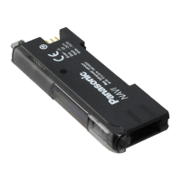
Amplier
Mounting
<How to mount the amplier>
1
Fit the rear part of the mounting
section of the amplier on a 35 mm
1.378 in width DIN rail.
2
Press down the rear part of the
mounting section of the unit on the
35 mm 1.378 in width DIN rail and
t the front part of the mounting
section to the DIN rail.
<How to remove the amplier>
1
Push the amplier forward.
2
Lift up the front part of the amplier
to remove it.
Note:
Be careful. If the front part is lifted without
pushing the amplier forward, the hook on
the rear portion of the mounting section is
likely to break.
<How to mount the sensor head>
1
Insert the sensor head connector
into the inlet until it clicks.
2
Fit the cover to the connector.
Wiring
Sensor head
connector
Cover
1
2
1
2
2
1
35mm 1.378 in width
DIN rail
 Loading...