- 7 -
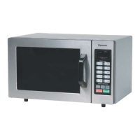
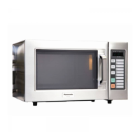
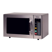
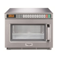
Outline Diagram
(1) Digital Display Window (see below)
(2) Memory Pads
(3) Power Level Selector Pad
(4) PROG.Pad
(5) STOP/RESET Pad
(6) DOUBLE QUANTITY (x 2) Pad
(7) START Pad
(8) Control Panel
(9) Door Safety Lock System
(10) Oven Window with HeaWapor Film
(Do Not Remove)
(11) Oven Lamp
(12) Splash Guard/Light Diffuser
Digital Display
Window Indicator
Locations
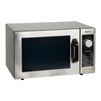
NE-1054F
Control Panel
(1)
(3)
(2)
(4)
(5)
(2)
(7)
(6)
(11)
(10)
(12)
(8)
(9)
A
-
PROG. Indicator
B
-
DOUBLE QUANTITY (x 2) Heating Indicator
C
-
Memory Pad Number and Heating Time Display (min.
sec.)
-
each indicator 0-9
D
-
Stage Heating Indicator - 3 maximum
E
-
Power Level Indicator
HI (HIGH)
M. HI (MEDIUM HIGH)
MED (MEDIUM)
LOW
DEF (DEFROST)
HOLD (Power OFF)
C
BA
E
D
IP5102_3BS80RP_Eng_10_150121.indd 7IP5102_3BS80RP_Eng_10_150121.indd 7 2015-1-21 10:00:332015-1-21 10:00:33
 Loading...