– 14 –
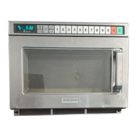
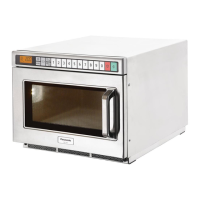
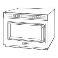
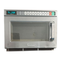
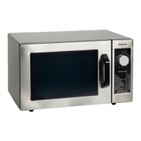
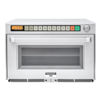
Outline Diagram
ProΙΙ
A B
1 2 3 4 5 6 7 8
A
PROG
PROG BUZZ
PROG LOCK
Digital Display Window
Power Level Indicator Display
Power Level Selector Pad (
)
Memory Shift Pad (
A B
)
Memory Pads
Stop/Reset Pad ( )
Start Pad ( )
Timer Dial
Oven Lamp Cover
Door Handle
Control Panel
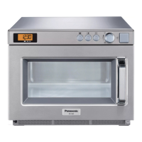
Air Filters
Program Entry Switch (behind Air Filters)
Buzzer Switch (behind Air Filters)
Program Lock Switch (behind Air Filters)
Middle Shelf
1
A
B
C
D
E
F
A
B
2 3
PROG
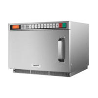
A - Program Display
B - Memory Area Code Display
C - Memory Pad Number Display
D - Stage Heating Indicator
E - Heating Time Display (min. sec.)
F - Power Level Indicator
HIGH
MEDIUM
LOW
DEFROST
STAND
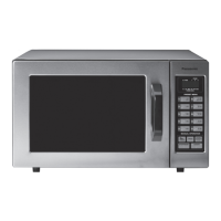
This oven is preset at the factory for the following:
X Manual operation
X Memory pads preset HIGH power at the indicated heating times for single stage heating
1 = 10 sec. 2 = 20 sec. 3 = 30 sec. 4 = 45 sec. 5 = 1 min.
6 = 1 min. 15 sec. 7 = 1 min. 30 sec. 8 = 2 min.
(There are two sides, A and B. Only A-side is preset.)
X Program Unlock
X Cycle Counter set to “0” on all pads
If you wish to change these times, please consult the operating instructions to find how to program them.
 Loading...