EasyManua.ls Logo

Panasonic NN-K574MF User Manual

Panasonic NN-K574MF
94 pages
To Next Page IconTo Next Page
Page #1 background imageLoading...
Page #1 background image
ORDER NO.SIMMC0408030A3
Microwave Oven
NN-S554MF NN-S554WF NN-K593MF / NN-K574MF NN-
K574WF / NN-K544WF /
HPE(Hong Kong)
YPQ(Singapore)
MPQ(Malaysia)
TPE(Thailand, Indonesia)
LPK(Philippines)
YTE(Others)
KTE(UAE)
KUE(Egypt)
PTE( Iran)
KPQ(Kuwait, Doha, Qatar, Oman, Bahrain, Pakistan)
STM(Saudi Arabia)
ZPE(CIS Countries)
Please file and use this manual together with the service manual for
Model NN-S553/K593/K573/K543 (ORDER NO. SIMMC0306022C3).
1
Question and Answer IconNeed help?

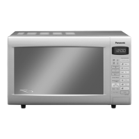
Do you have a question about the Panasonic NN-K574MF and is the answer not in the manual?

Panasonic NN-K574MF Specifications

General IconGeneral
TurntableYes
Child LockYes
TypeMicrowave Oven
Control TypeTouch Control
Cooking ModesMicrowave

Summary

PRECAUTIONS TO BE OBSERVED BEFORE AND DURING SERVICING TO AVOID POSSIBLE EXPOSURE TO EXCESSIVE MICROWAVE ENERGY

DANGER OF HIGH VOLTAGE AND HIGH TEMPERATURE (HOT/LIVE) OF THE INVERTER POWER SUPPLY (U)

INVERTER WARNING

Critical warnings about the high voltage inverter power supply circuit.

1. SCHEMATIC DIAGRAM

2. CAUTIONS TO BE OBSERVED WHEN TROUBLESHOOTING

2.2. Inverter warnings

3. MEASUREMENTS AND ADJUSTMENTS

3.1. Adjustment of primary latch switch, secondary latch switch and short switch.

Procedure for adjusting door latch and short switches for proper operation.

3.2. Measurement of microwave output

4. EXPLODED VIEW AND PARTS LIST

5. DIGITAL PROGRAMMER CIRCUIT

1. SCHEMATIC DIAGRAM (APH)

2. SCHEMATIC DIAGRAM (CPH)

4. PROCEDURE FOR MEASURING MICROWAVE ENERGY LEAKAGE

4.2. Procedure for measuring radiation leakage

Step-by-step guide for measuring microwave radiation leakage.

12. DIGITAL PROGRAMMER CIRCUIT (NN-T583SF APH/CPH) SCHEMATIC DIAGRAM

13. DIGITAL PROGRAMMER CIRCUIT(NN-T563SF APH, / NN-T563SAF APH) SCHEMATIC DIAGRAM

14. DIGITAL PROGRAMMER CIRCUIT(NN-S*** APH/ CPH) SCHEMATIC DIAGRAM

15. DIGITAL PROGRAMMER CIRCUIT PARTS LIST

CONTROL PANEL

OPERATION AND DIGITAL PROGRAMMER CIRCUIT TEST PROCEDURE

2. Time Cooking for Two Stage

Instructions for performing two-stage cooking sequences.

3. Inverter Turbo Defrost

Procedure for utilizing the Inverter Turbo Defrost function.

4. Inverter Auto Cooking

Steps for operating the Inverter Auto Cooking feature.

7. Sensor Cooking (NN-S560BFAPH/CPH,NN-S560WFAPH/CPH)

5. Sensor Reheat (NN-S560BFAPH/CPH,NN-S560WFAPH/CPH)

WARNING OF INVERTER POWER SUPPLY (U) GROUNDING

WARNING OF DISCHARGING HIGH VOLTAGE CAPACITORS

DISASSEMBLY AND PARTS REPLACEMENT PROCEDURE

1. Magnetron

Procedure for removing and replacing the magnetron.

2. Digital Programmer Circuit (DPC) and membrane key board.

Steps to remove the DPC and membrane keypad assembly.

3. Low voltage transformer and/or power relays (RY1, RY2)

Procedure for replacing the low voltage transformer and power relays.

5. Door assembly

8. Inverter Power Supply (U)

COMPONENT TEST PROCEDURE

1. Primary Latch Switch, Secondary (Secondary Latch Switch and Power Relay B) Interlocks.

Test procedure for door interlock switches and power relay B.

3. Magnetron

Test procedure for magnetron continuity and resistance.

5. Inverter Power Supply (U)for USA only

Specific test procedure for USA models of the Inverter Power Supply.

6. Steam Sensor and Digital Programmer Circuit

TROUBLESHOOTING GUIDE

2. Be careful of high voltage circuit.

Emphasizes caution when working with high voltage circuits.

3. Discharge high voltage capacitor.

Safety procedure to discharge high voltage capacitors before servicing.

HOW TO CHECK THE SEMICONDUCTORS USING AN OHM METER

Troubleshooting of Inverter Circuit (U) and Magnetron NEW H.V.

NOTE: DO NOT try to repair this Inverter Power Supply (U) and also DO NOT RE-ADJUST PRESET VOLUME on the board.

Critical warning against repairing or adjusting the Inverter Power Supply.

Trouble Related to Digital Programmer Circuit

Related product manuals