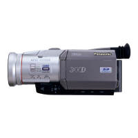
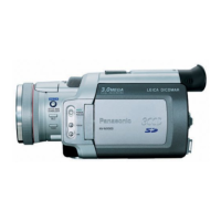
This document provides a service manual for the Panasonic NV-MX350EG / NV-MX350B / NV-MX350EN / NV-MX350A Digital Video Camera/Recorder, focusing on its Q3-Mechanism.
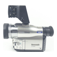
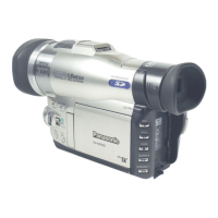
The Panasonic NV-MX350 series is a digital video camera/recorder designed for capturing and recording video. It offers various features for both video and audio recording, along with connectivity options for external devices and memory cards.
Important Technical Specifications:
- Power Source: DC 7.9 V / 7.2 V
- Power Consumption: 5.6 W (when using LCD monitor)
- Recording Format: Mini DV (Consumer Digital Video SD format)
- Video Recording System: Digital component recording
- Audio Recording System: PCM digital recording (12-bit 4 ch / 16-bit 2 ch)
- Video Playback Time: SP: 120 min, LP: 180 min (with DVM60)
- Image Sensor: 1/4 inch CCD image sensor (800,000 pixels)
- Lens: F1.8, f=3.3 - 33 mm (10x optical zoom)
- Filter Diameter: 43 mm
- Minimum Illumination: 0.8 lx (low light mode)
- Digital Still Picture: JPEG (640 x 480 pixels)
- LCD Monitor: 3.5-inch LCD
- EVF: 0.44-inch EVF
- Dimensions: Approximately 72 (W) x 90 (H) x 180 (D) mm
- Weight: Approximately 620 g (without battery and DV cassette)
Usage Features:
The camera supports MPEG4 recording and voice recording directly to a memory card, offering flexibility in media usage. It also features an external DV/VIDEO input for connecting other video sources. The device includes a mode select holder and buttons for various functions such as photo, card mode select, sub record, and reset. The LCD monitor and EVF provide visual feedback, and the camera incorporates a power LED that flashes to indicate undesirable conditions.
Maintenance Features:
The service manual outlines several procedures for maintenance and repair.
- Fuse Replacement: Instructions are provided for safely replacing the 5-ampere fuse in the AC mains plug, emphasizing the importance of using an approved replacement fuse (ASTA or BSI to BS1362) and ensuring the fuse cover is refitted.
- Capacitor Discharge: A critical safety procedure is detailed for discharging the capacitor on the Flash C.B.A. before disassembly, using 2 resistors (ERG2SJ221:220 ohm/2W) connected between CL7007 and GND for 3 seconds.
- EEPROM Data for Spare Parts: When replacing the Main C.B.A., the fixed and average data must be changed using a Tatsujin kit according to the movie camera's suffix.
- Service Extension Cables: Specific extension cables are required for checking or adjusting individual circuit boards, excluding module parts.
- Error Code Display: The camera can display error codes on the EVF or LCD monitor to assist in troubleshooting. Some critical errors (F31: Data Transmission Error, U10: Dew, U11: Head Clogging) are displayed automatically. For other errors, the FADE/STOP and REC START/PAUSE buttons must be pressed simultaneously for 3 seconds. This operation is not possible if a cassette tape is inserted.
- Lithium Battery Replacement: The procedure for replacing the lithium battery (VSB0407) involves removing the Side Case (R) Unit, unsoldering the old battery, and soldering a new one of the same type and manufacture, ensuring correct polarity.
- Disassembly Procedures: Detailed flowcharts and step-by-step instructions with figures are provided for disassembling various units, including the MF Hood Unit, Side Case (R) Unit, Lens Unit, Camera C.B.A., EVF / Rear Case Unit, Mecha. Unit & Main C.B.A., EVF C.B.A., and Monitor C.B.A.
- Electrical Adjustment Preparation: Instructions are given for unlocking the locking tab and removing the EVR connector, then connecting specific cables for electrical adjustments.
- Mechanical Adjustment: A mechanical adjustment table outlines procedures for tape running confirmation, linearity adjustment, B.E.R. value confirmation, capstan tilt adjustment, S3 base adjustment, and sub chassis adjustment. Tools and fixtures, such as precision drivers, gear drivers, cut washer jigs, and molyton grease, are specified for these tasks.
The manual also includes schematic diagrams, waveform tables, abbreviations, and parts lists for various sections of the camera, facilitating comprehensive servicing and repair.