1-19
1
NOTE
Wiring System Diagrams
L2
L1
U2
U1
L3
N
A
L1
L2
L3
N
U2
U1
L
N
1
2
2
1
D
B
L
N
2
1
C
(1) Refer to “Recommended Wire Length and Wire
Diameter for Power Supply System” for the
explanation of “A”, “B”, “C” and “D” in the above
diagrams.
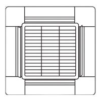
(2) The basic connection diagram of the indoor unit
shows the 7P terminal board, so the terminal boards
in your equipment may differ from the diagram.
(3) Refrigerant Circuit (R.C.) address should be set
before turning the power on.
L1 L2 L3 N
Outdoor Unit
5P terminal board
Power
supply
2P terminal board
Unit Control
Line
LN
U1
U2
R1
R2
Indoor Unit
7P terminal board
Power
supply
Remote
controller
line
Unit
control
wiring
E1 Type
Power supply*
220 – 240 V ~50/60 Hz
Remote
controller
WHT
BLK
* Regarding S-250PE1E8, the power supply is
220-240V, 50Hz only.
Ground
Ground
Ground
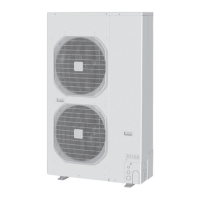
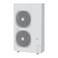
Outdoor unit (3-phase)
INV unit
Power supply
380 – 415 V, 3N, ~ 50/60 Hz
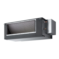
Indoor
unit
(1) When linking the outdoor units in a network, disconnect the terminal extended from the short plug
(CN003, 2P Black, location: right bottom on the outdoor main control PCB) from all outdoor units
except any one of the outdoor units. (When shipping: In shorted condition.)
(2)
Outdoor unit
Indoor unit Indoor unit Indoor unit
Outdoor unit Outdoor unit
Do not install the inter-unit control wiring in a way that forms a loop. (Fig. 1-1)
Fig. 1-1
Prohibited
Prohibited
CAUTION
SM830194-02BigPAC-i.indb19SM830194-02BigPAC-i.indb19 2012/09/0311:23:372012/09/0311:23:37
 Loading...