1-44
1
2
3
4
1
5
6
7
8
9
25
25
9 550
518
518
550
568
568
CL
62.4110110110
5
(106.3) 110 110 110 5.2
31
50
441.590
110
8-o4.5
1
1526
940
568
5
6
4
(316)
56
170 (110)660
20 10380
2021 340
60
(178)167 555
(303)
217
643
566
8
3
1
2
7
4. Dimensions of Air-Discharge Chamber :
In snowy regions, if there is concern that snow may enter the air
discharge chamber, remove the base of the
chamber before using.
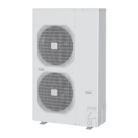
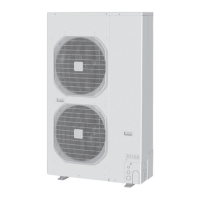
Reference diagram for U-200PE1E8 / U-250PE1E8
(Reverse side )
Unit: mm
Air intake
Reference diagram for air-discharge support (field supply) :
hole
Unit: mm
(Reverse side )
Air
discharge
Air
discharge
Air intake
Air intake
Air discharge support
Downward, Left side installation fixture T1.0
Downward, Right side installation fixture T1.0
Downward, Center side installation fixture T1.0
Upward, Left side installation fixture T1.0
Upward, Right side installation fixture T1.0
Upward, Left side installation fixture T1.0
Upward, Right side installation fixture T1.0
Sec1.indd 44 2014/11/07 10:28:00
 Loading...