1-80
1
Blower operation signal and protection signal
Power supply
SW1
X1 : Relay (field supply)
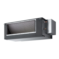
Limitation of AHU
When the AHU is selected, there are some limitations.
Cooling Heating
Max.
Max.
-10
(DB) (WB)-20
(DB)43 (WB)15
(DB)18
(DB)
16
(DB)
32
/23
(DB)30
Outdoor temperature
Blower protect input
Blower signal output
Inlet air temperature
(to the heat exchanger)
Min.
Min.
Max.
Min.
The limitation of Heat exchanger volume, Air volume and Front area is shown in the following
Table 1-10, 1-11 & 1-12.
The limitation of temperature range is shown below.
Table 1-10 : Inside volume of heat exchanger
Table 1-11 : Air volume of heat exchanger
Table 1-12 : Front area of heat exchanger
Cooling Capacity 20 kW 25 kW
1.0 m
2
1.0 m
2
0.54 m
2
0.66 m
2
Front area
1
2
3
4
X1
Minimum applicable load
DC 5 V, 1 mA
Maximum applicable load
AC 230 V, 2 A
SW 1 : operation command (field supply)
AC 220 ~240 V, 0.1 A
Max.
Min.
Cooling Capacity 20 kW 25 kW
3960 m
3
/h 4440 m
3
/h
1680 m
3
/h 2280 m
3
/h
Air volume
Max.
Min.
Cooling Capacity 20 kW 25 kW
4.3 dm
3
4.3 dm
3
2.3 dm
3
2.7 dm
3
Heat exchanger
volume
Sec1.indd 80 2014/11/07 10:28:11
 Loading...