e.
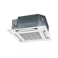
Ceiling
Air
Good example
Decorative panel
Cool air leakage
(no good)
Air conditioner unit
Air
Bad example
Ceiling
6. Adhere the cosmetic panel and ceiling wall
together and confirm no gap in between. Readjust
indoor unit height, if there is a gap between ceiling
wall and decorative panel although it have been
fixed by screw.
If there are no effect to the indoor unit level and
drain piping etc., the adjustment of indoor unit
height can be adjusted through the corner cover
hole. Tighten back firmly the fixing nut of indoor
unit after adjustment has been made.
7. Open the indoor control box cover. (2 pcs)
8. Insert firmly the connector of cosmetic louver to
indoor PCB CN-STM1 and CN-STM2.
Be caution not to clamp the cord in between
control board and control board cover.
9. After complete, install back removed part follow
opposite procedure.
Warning
Be sure to hook the air inlet grill string, to
prevent grill from falling and causing injury
from it.
When using the infrared remote controller, refer to the
instruction manual supplied with the infrared remote
controller (option) and the infrared receiver (option)
CN-STM1CN-STM2
and here
Louver motor wire
11.6.10 AS FOR TIMER OUTPUT
• Connect the timer cord to connector (CN-TIMER) on print circuit board.
Printed
circuit
board
Timer
Contact
Close: RUN
Open: STOP
d.c. 5V
CN-TIMER
2
1
Relay contact
Connector
Timer setting
• The connector must use XH-2 (housing) manufactured by J.S.T. Mfg. Co., Ltd.
• Wiring must use vinyl code with the sheath or cable line diameter 0.3mm
2
.
• The length of wiring should be within 150m and separated from power line in order to prevent malfunction.
• The input current is DC5V, and 1mA. The relay contact must use the contact for the minute electric current
suitable for this.

 Loading...