Do you have a question about the Panasonic U-8ME2E8 and is the answer not in the manual?
Warning about severe personal injury or death from electrical shock and wiring hazards.
Guidelines for tight wiring, exclusive power outlets, ELCB/circuit breakers, and grounding.
Care needed when lifting and moving indoor and outdoor units to prevent strain.
Guidelines for selecting installation locations like rooms, moist areas, high winds, and snowy areas.
Precautions for refrigerant leakages, mixing air, flame contact, and proper tubing connections.
Turn off power, keep fingers away from moving parts, clean up site. Warnings against modification.
Cautions regarding touching air inlet, aluminum fins, sitting on unit, or inserting objects into fan case.
Standards for minimum room volume based on partitions and openings for ventilation.
Comparison of minimum indoor floor space and refrigerant amount for density limits.
Process tubing requirements, bending radius, and preventing impurities from entering tubing.
Precautions for recharging refrigerant in liquid form and handling different tools for R410A.
How to determine main and sub outdoor units by setting O/U.ADD on the PCB.
Order of priority for outdoor units based on O/U.ADD setting.
Procedures for delayed start of units in the same system or across multiple systems.
Rules for stopping all outdoor units or individual units based on load reduction.
Table showing compressor types for different outdoor unit capacities.
Rules for determining compressor priority based on trip counter, operating time, and address.
How compressors start based on priority order.
How compressors stop based on priority order.
Procedure for starting two compressors simultaneously.
Table showing frequency ranges for inverter compressors based on unit type and conditions.
Compressor stop rules and exceptions for forced stops.
Control of compressor start/stop and frequency based on pressure and temperature sensors.
Cooling capacity adjustment to prevent freezing and dew.
Heating capacity adjustment and prevention of abnormal high-pressure.
Operation of the 4-way valve in cooling and heating modes, and during defrost.
Operation of the SAVE valve after outdoor unit stops and when high pressure is detected.
Purpose of the valve to recover oil from the oil separator.
Function of the valve for pushing oil in balance piping into other units.
Purpose of the valve to recover oil and refrigerant from the accumulator.
Function activated by refrigerant leakage signal from the indoor unit.
Operation of MOV4 to increase super-cooling in the double tube coil during cooling.
Conditions for turning ON the crankcase heater of the compressor when it stops.
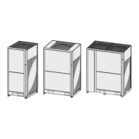
Details on the number of fan motors used in different outdoor unit types.
Control range of the DC fan motor in ordinary and high static-pressure modes.
Maximum and minimum rotation numbers for the fan based on cooling/heating mode.
Selecting silent mode for noise reduction, limiting fan mode and frequency.
Enabling high static pressure mode by changing EEPROM settings for specific units.
Control of MOV pulse for indoor units based on operating mode and thermostat status.
Control of MOV pulse for indoor units with RAP valve kit.
Operation of RAP valve kit to prevent refrigerant collection in the indoor heat exchanger.
Control of indoor fan speed during dry mode based on temperature difference and thermostat status.
Conditions for stopping the indoor unit fan in heating mode.
CCU intervention in drain pump control based on EEPROM settings.
States of oil level and judgment criteria for compressor oil.
How the oil level is detected using an oil sensor.
Recovery of oil from the oil separator to the compressor through ORVR.
Receiving oil from operating outdoor units when a unit falls into low oil level state.
Control time and operation of outdoor/indoor units for cooling.
Control time and operation of outdoor/indoor units for heating.
System uses reverse cycle defrost and outdoor unit cycle defrost.
Conditions that prevent defrost from restarting immediately after completion.
Conditions for detecting frost based on heat exchanger temperature.
Setting heating operation time to prohibit defrosting.
Conditions that determine the end of defrosting based on temperature and time.
How reverse cycle defrost is carried out for single outdoor unit systems.
Standard values for limit current and limited ratio against standard value.
Patterns of control when Energy Saving button is pressed, based on EEPROM settings.
Function for automatic backup operation when an alarm occurs.
Conventional method of backup operation by disconnecting failed outdoor units.
Automatic selection of cooling/heating mode based on indoor unit distribution and temperature.
System continues operation even if outdoor unit cannot communicate with some indoor units.
Diagram identifying various connectors and components on the main PCB.
Diagram of the High Insulation Current (HIC) PCB.
Diagram of the Outdoor Unit Filter (FIL) PCB.
Diagram of the Outdoor Unit Fan PCB.
Explanation of switches (SW1-SW7) and their functions for address and mode settings.
Electrical wiring diagram for specific outdoor unit models.
Electrical wiring diagram for specific outdoor unit models.
Electrical wiring diagram for specific outdoor unit models.
How room temperature is detected and thermostat operation based on temperature difference.
Functionality related to heating standby and intake air temperature control.
Control of indoor fan speed during automatic fan mode in cooling and heating.
Operation of MOV at 480 pulses in specific cases like factory shipment or after power connection.
Conditions under which the drain pump operates, including thermostat states and liquid temperature.
Automatic selection of heating/cooling mode based on indoor unit distribution and temperature.
Control of discharge air temperature to prevent dew condensation or manage thermostat OFF conditions.
Operation of RAP valve kit to prevent refrigerant collection in the indoor heat exchanger.
Selection of flap position based on operating mode and automatic movement when unit is stopped.
Display of filter sign on remote controller and procedure to reset it after cleaning.
Fan control during dry mode based on temperature difference and thermostat status.
Control of ventilation fan operation linked to indoor unit ON/OFF status.
Operation or stopping of indoor units separately using the T10 terminal.
Table of correction temperatures for various indoor unit types at factory shipment.
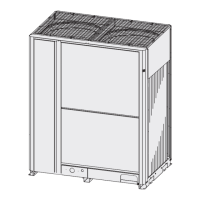
Procedure for removing front panels and covers from outdoor units of different HP types.
Procedures for discharging oil from the oil separator and checking the oil condition.
Automatic and manual backup operation functions for system continuity during repairs.
Procedures for recovering refrigerant from outdoor units and the entire system.
Pressure testing and soapy water methods to check for leaks in the outdoor unit.
Procedure to remove remaining refrigerant or gases from the repaired outdoor unit and tubing.
Procedures for charging compressor oil into the outdoor unit and oil-charging tank.
Procedures for pumping out refrigerant from the outdoor unit for maintenance or repairs.
Diagnosis and replacement procedures for compressor failures, including dry core cleaning.
Introduction to the CZ-RTC4 maintenance remote controller and its connection.
Overview of functions available on the ordinary display and mode settings.
Details on connecting the remote controller and using its display controls.
Procedures for displaying indoor and outdoor unit sensor temperatures.
How to view and clear outdoor unit alarm history using the remote controller.
Procedures for changing settings like item code and setting data using setting mode 1.
Procedure for setting filter lifetime, operating mode priority, and central control address.
Procedure for setting system, indoor unit, and group control addresses, and temperature shifts.
Overview of servicing functions like test run, sensor display, and auto address setting.
Table listing possible causes of malfunction and corresponding remote controller display codes.
Meaning of LED indicators on the outdoor unit control panel during auto address setting and alarms.
List of alarm codes, their meanings, probable causes, and corresponding page numbers.
Pre-operation checks including removing transportation parts and connecting power.
Step-by-step flowchart for performing the test run operation, including checks and corrections.
Diagram and explanation of switches and connectors on the main outdoor unit PCB.
Procedures for setting system addresses for indoor and outdoor units, with and without link wiring.
Procedures for initiating test run mode using CZ-RTC5A and CZ-RTC4 remote controllers.
Warning regarding refrigerant collection limits and proper procedure for pump down.
Table correlating remote controller alarm displays with detected contents and causes.
| Brand | Panasonic |
|---|---|
| Model | U-8ME2E8 |
| Category | Air Conditioner |
| Language | English |