5
6
Power
supply
Power
supply
Power
supply
Power
supply
NP
NP
NP
NP
NP
NP
NP
NP
Electric lock
(Electric vehicle gate lock)
*1
12 VAC/DC
12 VAC/DC
12 VAC/DC
12 VAC/DC
220-240 VAC
24 V DC
Electric lock
(Electric vehicle gate lock)
*1
Electric lock
(Electric door lock)
*2
Electric lock
(Electric door lock)
*2
DA
D
E
B
C
Connection device for option
output (A contact)
*1 Make sure to only connect electric vehicle gate locks to the S3/S4
terminals of the door stations.
*2 Make sure to only connect electric door locks to the S1/S2 terminals
of the door stations.
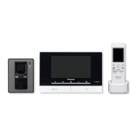
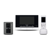
Main Monitor Station
Door Station 1
Door Station 2
Power Supply Unit
NP: Non-polarised
VL
VL
-
-
SWD501EX wiring schematic diagram
SWD501EX wiring schematic diagram
 Loading...