ScrewA
Youcanusethe[Wide/Zoomsettings]settingonthemainmonitortoselecttheareathat
isvisiblewhenavisitorcalls;availablesettingsare[Wide],[Zoom],and[All](entireimage
display).(Defaultsetting:[Wide])
● Thefollowingvaluesareforwhenthedoorphoneisinstalledinthestandardposition(thecentre
of thedoorphone’s height isapproximately1,450mm) and at adistanceof approximately
500mmfromthecameralens.
■ Installation height and area visible by the camera lens
When set to zoom
Displaysaportionofthewideimageat2timesthesize.
● Because a digital zoom is used, the image quality of zoom
displayislowerthanthatofwidedisplayorentireimagedisplay.
Imagedisplayedon
mainmonitor:
● Youcan use the mainmonitor’s [Zoom positionsettings] settingto select thedesired area
visiblewhenzooming.
Refertothefollowingandcongurethemainmonitor.
Entire image display
Theareaaboveandbelowthewideimageisvisible.
Important:
● Onthebottomsurface of thedoorphoneandthe mountingbase,thereare holes toallowwater
todrain.Donotcoverthemupwheninstalling.
● Whenexistingwiring(suchaschimewires)isused:
- ItmaycontainACvoltagethatmaycauseelectricshockand/ordamagetheproduct.
- Neverusethefollowingtypesofwiring.Consultaqualiedtechnician/dealer.
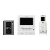
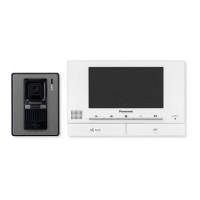
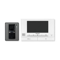
VL-V554EX VL-V554UEX
1
Attachthemountingbasetothewallsecurely.
Mountingbase
(accessory)
Wire(locallyprocured)
Wall
83.5mm
Screws(locallyprocured)×2
● Installthemountingbaseonaverticalatwall.
1
Installtheflushmountingboxinthe
wall.
Flushmountingbox(accessory)
100mm
Knockouthole
*1
151mm
37mm
*1Onlyopentheknockoutholesas
requiredforthewiring.
2
Useahexwrench(accessory)toloosenscrewAandremovethefrontpanelofthedoor-
phone.
ScrewA
Frontpanel
2mmhexwrench
(accessory)
3
Connectthewires.
Terminalforthe
mainmonitor
<Rear
view>
Terminalsfortheelectriclocks
● Recommendedtorque:
0.5N·m{5.1k
g
f·cm}
● Maximumtorque:
0.7N·m{7.1k
g
f·cm}
3-1Loosenthescrews.
3-2Pushinthewirestotheterminalconnectors(non-polar),thentightenthescrews.
4
Attachthedoorphonetothemounting
base.
Screws(accessory)×4
4
Attachthedoorphonetotheflushmounting
box.
Screws(accessory)×4
5
AttachthenameplatetothedoorphoneandusescrewAtosecurethefrontpanel.
● Writethenameonthenameplateasneeded.
Nameplate
(accessory)
ScrewA
● Recommended torque:
0.35N·m{3.6k
g
f·cm}
Approx.500
Approx.170°
Approx.2,250
Imagerange
Approx.115°
Approx.500
Imagedisplayedon
mainmonitor:
Approx.1,600
Approx.650
Approx.1,450
Upanddown
Leftandright(whenlookingfromabove)
Up
Imagerange
Approx.2,050
Approx.500
Centreof
doorphone
Approx.45°
Centre (default)
Approx.45°
Approx.500
Imagerange
Approx.1,650
Down
Approx.45°
Approx.500
Approx.1,400
Imagerange
Left
Approx.1,500
Approx.1,450
Approx.550
Approx.1,450
Approx.1,250
Approx.400
Installing the doorphone
■
About the installation location
● Thedevicemustbeinstalledinsideanelectricalpanelorcabinet.
● Areadilyaccessibledisconnectdeviceshallbeincorporatedexternaltotheequipment.
■
Precautions for wiring
● Makesureyouturnoffthepoweratthebreakerbeforeperforminganywiringwork.
● Always connect AC or DC cables to the appropriate connection terminals. Incorrectly
connectingtheACorDCcablesmaydamagethepowersupplyunit.
● Toprevent thepower cablesfrom disconnecting andtoprevent electricshock, securethe
powercablesusingthecablebinders(accessory)andattachthecablecovers.
How to connect the power cable (AC/DC)
1
StriptheAC/DCcablesasfollows:
7mm
45mm
<ACcable>
<DCcable>
25mm
7mm
2
Removethescrews(
B
)andthenremove
thecablecovers(
A
).
3
ConnecttheAC/DCcabletotheACIN
terminal/DCOUTterminalonthetopand
bottomofthepowersupplyunit,andthen
securethewiresbytighteningthescrews.
● Recommendedtorque:
- ACterminal:0.4N·m{4.1k
g
f·cm}
- DCterminal:0.45N·m{4.6k
g
f·cm}
<Frontview>
ACcable
*1
DCcable
Screws
*1
Cablebinders(accessory)
4
Usethecablebinders(accessory)to
securetheAC/DCcables(double-coated
area)tothepowersupplyunit.
5
Makesuretoreplacethecablecovers(
A
).
Connectthepowersupplyunit(accessory)andAC/DCcables(locallyprocured).
CAUTION
Insertthecablesfirmlyalltheway
intotheterminals.
Ifthecablesarenotinsertedall
theway,heatmaybegenerated.
*1Makesurethattherearenobarewires
exposedoutsidetheproduct.
Screws(
B
)
Cablecovers(
A
)
DCOUTterminal
ACcable
binderhole
ACINterminal
<Topview>
<Bottomview>
DCcable
binderhole
Power supply unit (with cable covers
removed)
Attach to the DIN rail
Attachintheorderdescribedbelowsothathook(b)ispositionedatthebottom.
1
Hanghook(a)ontheDINrail(
A
).
2
Pullandholdtheleverdown(
B
).
3
Securehook(b)totheDINrail(
C
).
Hook(a)
A
B
C
Hook(b)
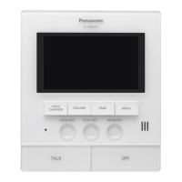
Main monitor installation position
Installing the main monitor
Mainmonitor
installationposition
82.5mm
82.7mm
2
ConnecttheDCcableandwires.
● Connect thewirescorrectly accordingto "Wiringschematic
diagram".
3
Mountthemainmonitortothemountingbracket.
3-1 Lineupthetabonthebottomofthebracketwiththegrooveonthemainmonitor(
A
).
3-2 Lineupthetabonthetopofthebracketwiththegrooveonthemainmonitor,and
pushthemainmonitordownuntilitissecure(
B
).
Wall
1
Attachthemountingbrackettothewall
securely.
● Installthe mounting bracketona vertical
atwall.
A
RemovescrewAandthenremovethe
terminalcover.
B
LoosenscrewBandpushinthewiresof
theDCcabletotheterminalconnectors
(non-polar),thentightenthescrews.
● Recommendedtorque:
0.8N·m{8.2k
g
f·cm}
C
Usethecablebinder(accessory)to
securetheDCcable(double-coated
area)tothemainmonitor.
D
Makesuretoreplacetheterminalcover.
How to connect the DC cable:
Whilepressingonthebuttonwithapoint-
edobjectsuchasascrewdriver,insert
thewireintotheterminalconnector.(To
disconnectawire,whilepressingonthe
button,pulloutthewire.)
Barewireattip
9mm
Terminal
Button
Wiringfrom
doorphone
Important:
Donotconnectthepowercable.
(Damagemayoccur.)
How to make wiring connections:
Resetbutton
SDcard
slot
20cm
20cm
20cm
20cm
Cablebinder
(accessory)
12mm
Barewireattip
ScrewB
● Forthefollowingreasons,leaveatleast20cmofspace
above,below,and totheleft andrightsidesof themain
monitor:
-Topreventmalfunctionandsoundcuttingout
-ToensureSDcardscanbeinsertedandremoved,
andtomakesuretheresetbuttoncanbeused
(theSDcardslotisonthesideofthemainmonitor;
theresetbuttonisonthebottom)
■
About the installation position of the main monitor and mounting bracket
● Placethemainmonitorinalocationthatyoureyesarethesameheightasthecentre
ofthedisplay.
● Afterdecidingwheretoinstallthemainmonitor,attach
the mounting bracket in the location shown on the
right.
Doorphone installation position
Installing the power supply unit
Imagerange:
Approx.900
Approx.500
Approx.85°
Approx.170°
Centre (default)
Imagerange:
Approx.900
Approx.85°
Right
Imagerange:
Approx.900
Approx.500
Approx.170°
Approx.85°
Approx.500
Approx.850
Approx.1,450
Approx.550
32mm
When set to wide (default)
Centreof
doorphone
Centreof
doorphone
Centreof
doorphone
Approx.95°
Centreof
doorphone
Approx.1,450
Approx.500
Approx.900
Approx.170°
Approx.500
Approx.1,100
Approx.2,000
Imagerange
Imagedisplayedon
mainmonitor:
Viewwhenlooking
fromabove
Viewwhenlooking
fromabove
(Units:mm)
Notes about electrical wiring
Makesurenottopinchthewires(asshowntothe
right)onthemountingbracketwheninstalling.
● Donotforciblyattachtothemountingbracket.
Vertical,flatwall
Screws
(locallyprocured)
Holeinwall
83.5
60
7
50
Mountingbracket
(Units:mm)
(Units:mm)
(Units:mm)
(Units:mm)

 Loading...